The use of thermography to design tissue flaps - experimental studies on animals
- PMID: 25337153
- PMCID: PMC4198642
- DOI: 10.5114/wiitm.2014.44056
The use of thermography to design tissue flaps - experimental studies on animals
Abstract
Introduction: Methods allowing one to locate the position of a cutaneous perforator do not allow one to determine the boundaries of the vascularized skin. In clinical practice this causes complications in the form of marginal necrosis of the flap.
Aim: To examine the usefulness of thermography to assess the extent of vascularization of the skin and subcutaneous tissue by a single perforator.
Material and methods: Thirty-one male rats were used. Using dynamic thermography the perforators on the abdominal skin were located. Afterwards the flap was prepared on a randomly chosen perforator. After 24 h the extent of vascularization of the skin by a single perforator was examined.
Results: In 22.5% of cases the number of perforators marked in the thermography was equal to the number of perforators marked intraoperatively, in 64.5% it was lower and in 13% higher. The use of thermography has shown that basing the flap vascularization on the perforator with low efficiency resulted in statistically more frequent occurrence of ischemia and partial necrosis of the flap (p = 0.024). Partial necrosis of the flap occurred in 12 of 31 cases, always in the area in which during the preoperative thermography no perforators were found. The areas of necrosis occurred irrespectively of the distance from the supplying vessel.
Conclusions: When designing the shape of the flap, the distribution of all perforators must be considered. The perforators need to be included in the area of prepared tissues because their location indicates the area with a more efficient network of vessels.
Keywords: flap; perforator; thermography.
Figures
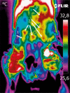

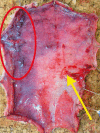
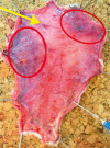
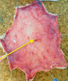


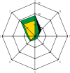
 , borders of the healthy tissue areas: green color
  , borders of the areas containing other perforators: yellow color
  . The directions on the chart are indicated by the numbers 1–8, direction 1 refers to the cephalad part of the flap, direction 5 refers to the caudad part of the flap
Similar articles
-
Evaluation of dynamic infrared thermography as an alternative to CT angiography for perforator mapping in breast reconstruction: a clinical study.BMC Med Imaging. 2016 Jul 15;16(1):43. doi: 10.1186/s12880-016-0144-x. BMC Med Imaging. 2016. PMID: 27421763 Free PMC article. Clinical Trial.
-
Dynamic InfraRed Thermography (DIRT) in DIEP-flap breast reconstruction: A review of the literature.Eur J Obstet Gynecol Reprod Biol. 2019 Nov;242:47-55. doi: 10.1016/j.ejogrb.2019.08.008. Epub 2019 Aug 23. Eur J Obstet Gynecol Reprod Biol. 2019. PMID: 31563818 Review.
-
[Smartphone-based thermography for perforator localisation in microvascular breast reconstruction].Handchir Mikrochir Plast Chir. 2018 Apr;50(2):111-117. doi: 10.1055/s-0043-114006. Epub 2018 Apr 19. Handchir Mikrochir Plast Chir. 2018. PMID: 29672783 German.
-
Using dynamic infrared thermography to optimize color Doppler ultrasound mapping of cutaneous perforators.Med Ultrason. 2015 Dec;17(4):503-8. doi: 10.11152/mu.2013.2066.174.dyn. Med Ultrason. 2015. PMID: 26649346
-
Redefining Vascular Anatomy of Posterior Tibial Artery Perforators: A Cadaveric Study and Review of the Literature.Ann Plast Surg. 2016 Jun;76(6):705-12. doi: 10.1097/SAP.0000000000000258. Ann Plast Surg. 2016. PMID: 25003444 Review.
Cited by
-
An Experimental and Clinical Study of Flap Monitoring with an Analysis of the Clinical Course of the Flap Using an Infrared Thermal Camera.Bioengineering (Basel). 2024 Jul 7;11(7):688. doi: 10.3390/bioengineering11070688. Bioengineering (Basel). 2024. PMID: 39061770 Free PMC article.
-
Thermal imaging in biomedical research: a non-invasive technology for animal models.Front Vet Sci. 2025 Feb 24;12:1544112. doi: 10.3389/fvets.2025.1544112. eCollection 2025. Front Vet Sci. 2025. PMID: 40066193 Free PMC article. Review.
-
Thermal Imaging as a Method to Indirectly Assess Peripheral Vascular Integrity and Tissue Viability in Veterinary Medicine: Animal Models and Clinical Applications.Animals (Basel). 2023 Dec 31;14(1):142. doi: 10.3390/ani14010142. Animals (Basel). 2023. PMID: 38200873 Free PMC article. Review.
References
-
- Smit JM, Klein S, Werker PM. An overview of methods for vascular mapping in the planning of free flaps. J Plast Reconstr Aesthet Surg. 2010;63:674–82. - PubMed
-
- Mathes DW, Neligan PC. Current techniques in preoperative imaging for abdomen-based perforator flap microsurgical breast reconstruction. J Reconstr Microsurg. 2010;26:3–10. - PubMed
-
- de Weerd L, Mercer JB, Setså LB. Intraoperative dynamic infrared thermography and free-flap surgery. Ann Plast Surg. 2006;57:279–284. - PubMed
-
- de Weerd L, Miland AO, Mercer JB. Perfusion dynamics of free DIEP and SIEA flaps during the first postoperative week monitored with dynamic infrared thermography. Ann Plast Surg. 2009;62:42–7. - PubMed
-
- Zetterman E, Salmi AM, Suominen S, et al. Effect of cooling and warming on thermographic imaging of the perforating vessels of the abdomen. Eur J Plast Surg. 1999;22:58–61.
LinkOut - more resources
Full Text Sources
Other Literature Sources
