

Dual optimization method of radiofrequency and quasistatic field simulations for reduction of eddy currents generated on 7T radiofrequency coil shielding
- PMID: 25367703
- PMCID: PMC4515214
- DOI: 10.1002/mrm.25424
Dual optimization method of radiofrequency and quasistatic field simulations for reduction of eddy currents generated on 7T radiofrequency coil shielding
Abstract
Purpose: To optimize the design of radiofrequency (RF) shielding of transmit coils at 7T and reduce eddy currents generated on the RF shielding when imaging with rapid gradient waveforms.
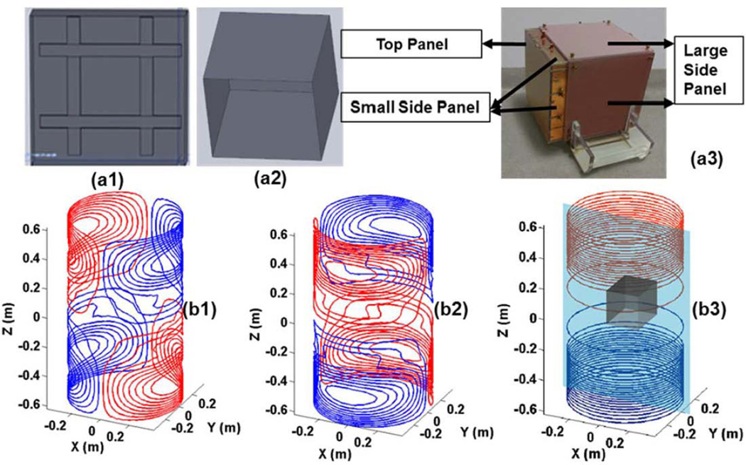
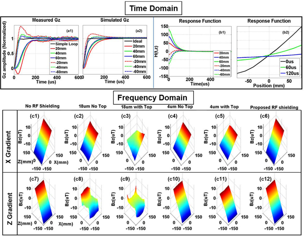
Methods: One set of a four-element, 2 × 2 Tic-Tac-Toe head coil structure was selected and constructed to study eddy currents on the RF coil shielding. The generated eddy currents were quantitatively studied in the time and frequency domains. The RF characteristics were studied using the finite difference time domain method. Five different kinds of RF shielding were tested on a 7T MRI scanner with phantoms and in vivo human subjects.
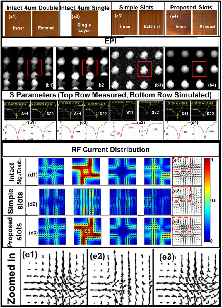
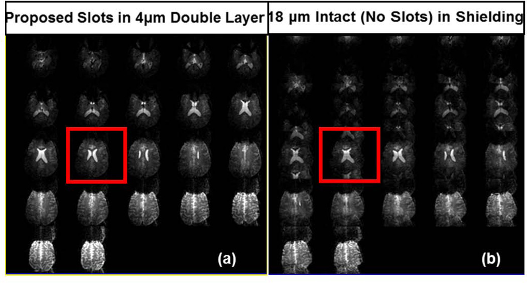
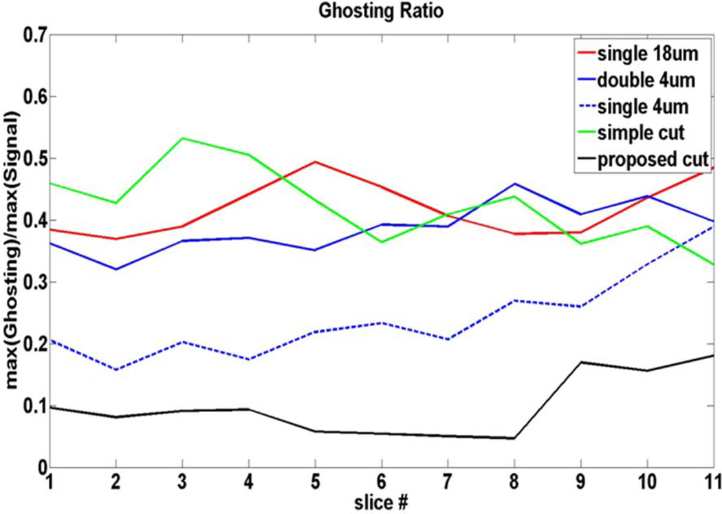
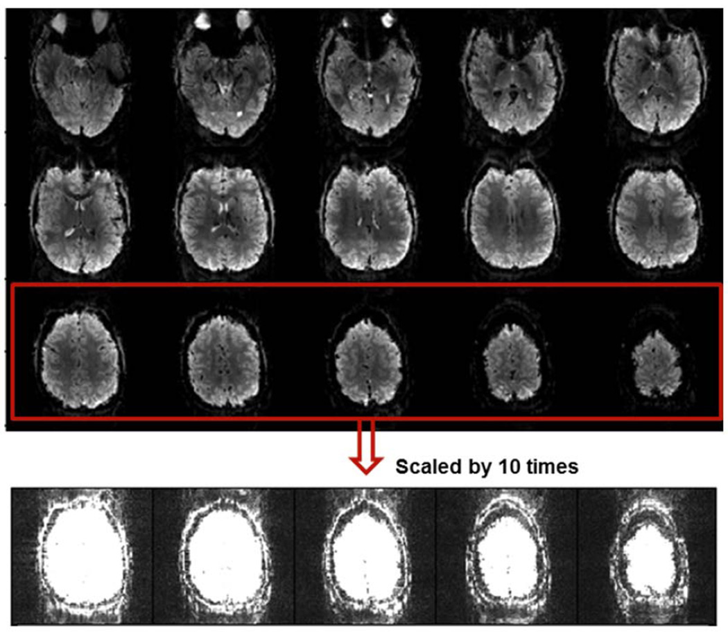
Results: The eddy current simulation method was verified by the measurement results. Eddy currents induced by solid/intact and simple-structured slotted RF shielding significantly distorted the gradient fields. Echo-planar images, B1+ maps, and S matrix measurements verified that the proposed slot pattern suppressed the eddy currents while maintaining the RF characteristics of the transmit coil.
Conclusion: The presented dual-optimization method could be used to design RF shielding and reduce the gradient field-induced eddy currents while maintaining the RF characteristics of the transmit coil.
Keywords: 7T MRI; RF shielding; Tic-Tac-Toe RF coil; echo-planar imaging; eddy current simulation; full wave RF simulation; gradient coil model.
© 2014 Wiley Periodicals, Inc.
Figures
Similar articles
-
RF shimming strategy for an open 60-channel RF transmit 7T MRI head coil for routine use on the single transmit mode.Magn Reson Med. 2025 Oct;94(4):1804-1816. doi: 10.1002/mrm.30563. Epub 2025 May 20. Magn Reson Med. 2025. PMID: 40391665 Free PMC article.
-
Characterization and reduction of gradient-induced eddy currents in the RF shield of a TEM resonator.Magn Reson Med. 2002 Aug;48(2):404-7. doi: 10.1002/mrm.10226. Magn Reson Med. 2002. PMID: 12210952
-
Low eddy current RF shielding enclosure designs for 3T MR applications.Magn Reson Med. 2018 Mar;79(3):1745-1752. doi: 10.1002/mrm.26766. Epub 2017 Jun 6. Magn Reson Med. 2018. PMID: 28585334 Free PMC article.
-
High-performance radiofrequency coils for (23)Na MRI: brain and musculoskeletal applications.NMR Biomed. 2016 Feb;29(2):96-106. doi: 10.1002/nbm.3379. Epub 2015 Sep 24. NMR Biomed. 2016. PMID: 26404631 Free PMC article. Review.
-
Radiofrequency Coils for 7 Tesla MRI.Top Magn Reson Imaging. 2019 Jun;28(3):145-158. doi: 10.1097/RMR.0000000000000206. Top Magn Reson Imaging. 2019. PMID: 31188273 Review.
Cited by
-
Ultra-high-field RF coil development for evaluating upper extremity imaging applications.NMR Biomed. 2016 Dec;29(12):1768-1779. doi: 10.1002/nbm.3582. Epub 2016 Nov 3. NMR Biomed. 2016. PMID: 27809383 Free PMC article.
-
Development of a 7 T RF coil system for breast imaging.NMR Biomed. 2017 Jan;30(1):10.1002/nbm.3664. doi: 10.1002/nbm.3664. Epub 2016 Nov 11. NMR Biomed. 2017. PMID: 27859861 Free PMC article.
-
Improved 7 Tesla transmit field homogeneity with reduced electromagnetic power deposition using coupled Tic Tac Toe antennas.Sci Rep. 2021 Feb 9;11(1):3370. doi: 10.1038/s41598-020-79807-9. Sci Rep. 2021. PMID: 33564013 Free PMC article.
-
Computational and experimental evaluation of the Tic-Tac-Toe RF coil for 7 Tesla MRI.PLoS One. 2019 Jan 10;14(1):e0209663. doi: 10.1371/journal.pone.0209663. eCollection 2019. PLoS One. 2019. PMID: 30629618 Free PMC article.
-
In-vivo and numerical analysis of the eigenmodes produced by a multi-level Tic-Tac-Toe head transmit array for 7 Tesla MRI.PLoS One. 2018 Nov 27;13(11):e0206127. doi: 10.1371/journal.pone.0206127. eCollection 2018. PLoS One. 2018. PMID: 30481187 Free PMC article.
References
-
- Truhn D, Kiessling F, Schulz V. Optimized RF shielding techniques for simultaneous PET/MR. Med Phys. 2011;38(7):3995–4000. - PubMed
-
- Jehenson P, Westphal M, Schuff N. Analytical Method for the Compensation of Eddy-Current Effects Induced by Pulsed Magnetic-Field Gradients in Nmr Systems. J Magn Reson. 1990;90(2):264–278.
-
- Trakic A, Wang H, Liu F, Lopez HS, Crozier S. Analysis of transient eddy currents in MRI using a cylindrical FDTD method. Ieee T Appl Supercon. 2006;16(3):1924–1936.
-
- Tang F, Lopez HS, Freschi F, Smith E, Li Y, Fuentes M, Liu F, Repetto M, Crozier S. Skin and proximity effects in the conductors of split gradient coils for a hybrid Linac-MRI scanner. J Magn Reson. 2014;242C:86–94. - PubMed
-
- Sanchez Lopez H, Freschi F, Trakic A, Smith E, Herbert J, Fuentes M, Wilson S, Liu L, Repetto M, Crozier S. Multilayer integral method for simulation of eddy currents in thin volumes of arbitrary geometry produced by MRI gradient coils. Magn Reson Med. 2014;71(5):1912–1922. - PubMed
Publication types
MeSH terms
Substances
Grants and funding
LinkOut - more resources
Full Text Sources
Other Literature Sources
Medical
