. 2015 Apr;62(4):1077-88.
doi: 10.1109/TBME.2014.2367233.

Robotic system for MRI-guided stereotactic neurosurgery

Robotic system for MRI-guided stereotactic neurosurgery

Gang Li et al. IEEE Trans Biomed Eng. 2015 Apr.

Abstract

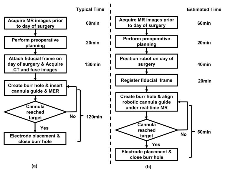
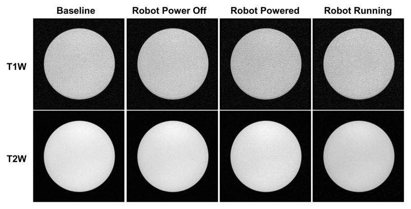
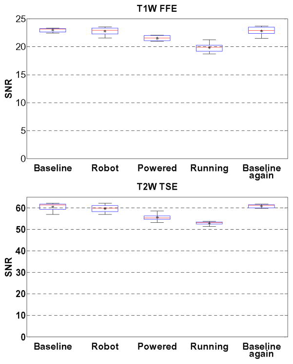
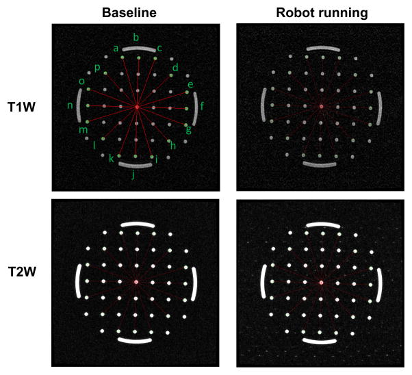
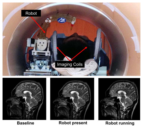
Stereotaxy is a neurosurgical technique that can take several hours to reach a specific target, typically utilizing a mechanical frame and guided by preoperative imaging. An error in any one of the numerous steps or deviations of the target anatomy from the preoperative plan such as brain shift (up to mm), may affect the targeting accuracy and thus the treatment effectiveness. Moreover, because the procedure is typically performed through a small burr hole opening in the skull that prevents tissue visualization, the intervention is basically “blind” for the operator with limited means of intraoperative confirmation that may result in reduced accuracy and safety. The presented system is intended to address the clinical needs for enhanced efficiency, accuracy, and safety of image-guided stereotactic neurosurgery for deep brain stimulation lead placement. The study describes a magnetic resonance imaging (MRI)-guided, robotically actuated stereotactic neural intervention system for deep brain stimulation procedure, which offers the potential of reducing procedure duration while improving targeting accuracy and enhancing safety. This is achieved through simultaneous robotic manipulation of the instrument and interactively updated in situ MRI guidance that enables visualization of the anatomy and interventional instrument. During simultaneous actuation and imaging, the system has demonstrated less than 15% signal-to-noise ratio variation and less than 0.20 geometric distortion artifact without affecting the imaging usability to visualize and guide the procedure. Optical tracking and MRI phantom experiments streamline the clinical workflow of the prototype system, corroborating targeting accuracy with three-ax- s root mean square error 1.38 ± 0.45 mm in tip position and 2.03 ± 0.58° in insertion angle.


Figures

Fig. 1
Fig. 1
Workflow comparison of manual frame-based approach and MRI-guided robotic approach for unilateral DBS lead placement. (a) Workflow of a typical lead placement with measured average time per step. (b) Workflow of an MRI-guided robotic lead placement with estimated time per step.
Fig. 2
Fig. 2
Configuration of the MRI-guided robotic neurosurgery system. The stereotactic manipulator is placed within the scanner bore and the MRI robot controller resides inside the scanner room. The robot controller communicates with the control computer within the Interface Box through a fiber optic link. The robot control software running on the control computer communicates with 3D Slicer navigation software through OpenIGTLink.
Fig. 3
Fig. 3
Equivalence of the degrees of freedom of a traditional manual stereotactic frame (left) and the proposed robotic system (right). Translation DOF in red, rotational DOF in green.
Fig. 4
Fig. 4
Exploded view of the RCM orientation module, showing (1) instrument/electrode, (2) headstock with cannula guide, (3) parallel linkage mechanism, (4) manipulator base frame, (5) flange bearings, (6) pulleys, (7) timing belts, (8) rotary encoders, (9) encoder housings, (10) pulleys, (11) eccentric locking collars, (12) rotary piezoelectric motors, (13) manipulator base.
Fig. 5
Fig. 5
Exploded view of the Cartesian motion module, showing (14) Scott-Russell scissor mechanism, (15) lead-screw, (16) nut, (17) motor coupler, (18) motor housing, (19) linear encoder, (20) linear piezoelectric motor, (21) linear guide, (22) horizontal motion stage, (23) lateral motion stage.
Fig. 6
Fig. 6
Reachable workspace of the stereotactic neurosurgery robot overlaid on a representative human skull. The red ellipsoid represents the typical DBS treatment target, i.e. the basal ganglia area.
Fig. 7
Fig. 7
Block diagram of the MRI robot control system. The power electronics and piezoelectric actuator drivers are contained in a shielded enclosure and connected to an interface unit in the console room through a fiber optic Ethernet connection.
Fig. 8
Fig. 8
Block diagram showing the key components of a piezoelectric motor driver card-based module.
Fig. 9
Fig. 9
MRI of the homogeneous section of the phantom in four configurations with two imaging protocols demonstrating visually unobservable image artifacts.
Fig. 10
Fig. 10
Boxplots showing the range of SNR values for each of five robot configurations evaluated in two clinically appropriate neuro imaging protocols (T1W FFE & T2W TSE). The configurations include Baseline (no robotic system components present in room), Robot (robot presented but not powered), Powered (Robot connected to power on controller), Running (Robot moving during imaging), and a repeated baseline with no robotic system components present.
Fig. 11
Fig. 11
Geometric patterns of the non-homogeneous section of the phantom filled with pins and arches for the two extreme robot configurations and the same two imaging protocols. The overlaid red line segments indicates the measured distance for geometric distortion evaluation.
Fig. 12
Fig. 12
Qualitative analysis of image quality. Top: Patient is placed inside scanner bore with supine position and robot resides on the side of patient head. Bottom: T2 weighted sagittal images of brain taken with three configurations: no robot in the scanner (bottom-left), controller is powered but motor is not running (bottom-middle) and robot is running (bottom-right).
Fig. 13
Fig. 13
Example of real-time MR imaging capabilities at 1.4Hz during needle insertion. Shown at (a) Initial position, (b) 25mm depth, (c) 45mm depth, and (d) 55mm insertion depth into a phantom.
Fig. 14
Fig. 14
Coordinate frames of the robotic system for registration of robot to MR image space
Fig. 15
Fig. 15
Configuration of the robotic device within scanner bore for the MR image-guided accuracy study.
Fig. 16
Fig. 16
Plot of intersection of multiple insertion pathways at a given target location based on segmentation of the MRI data. Each axis is 40mm in length. Inset: MRI image of phantom with inserted ceramic cannula.

References

    1. Hartkens T, Hill D, Castellano-Smith A, Hawkes D, Maurer C, Martin A, Liu H, Truwit C. Measurement and analysis of brain deformation during neurosurgery. Medical Imaging, IEEE Transactions on. 2003;22:82–92. - PubMed
    1. Starr PA, Martin AJ, Ostrem JL, Talke P, Levesque N, Larson PS. Subthalamic nucleus deep brain stimulator placement using high-field interventional magnetic resonance imaging and a skull-mounted aiming device: technique and application accuracy. Journal of Neurosurgery. 2010;112(3):479–490. - PMC - PubMed
    1. Larson P, Starr PA, Ostrem JL, Galifianakis N, Palenzuela MSL, Martin A. 203 application accuracy of a second generation interventional MRI stereotactic platform: initial experience in 101 DBS electrode implantations. Neurosurgery. 2013;60:187.
    1. Varma T, Eldridge P, Forster A, Fox S, Fletcher N, Steiger M, Littlechild P, Byrne P, Sinnott A, Tyler K, et al. Use of the NeuroMate stereotactic robot in a frameless mode for movement disorder surgery. Stereotactic and functional neurosurgery. 2004;80(1–4):132–135. - PubMed
    1. Masamune K, Kobayashi E, Masutani Y, Suzuki M, Dohi T, Iseki H, Takakura K. Development of an MRI-compatible needle insertion manipulator for stereotactic neurosurgery. Journal of Image Guided Surgery. 1995;4:242–248. - PubMed

Publication types