. 2014 Jun 24;8(3):034117.
doi: 10.1063/1.4884306. eCollection 2014 May.

Dean flow-coupled inertial focusing in curved channels

Affiliations

Dean flow-coupled inertial focusing in curved channels

Harisha Ramachandraiah et al. Biomicrofluidics. .

Abstract

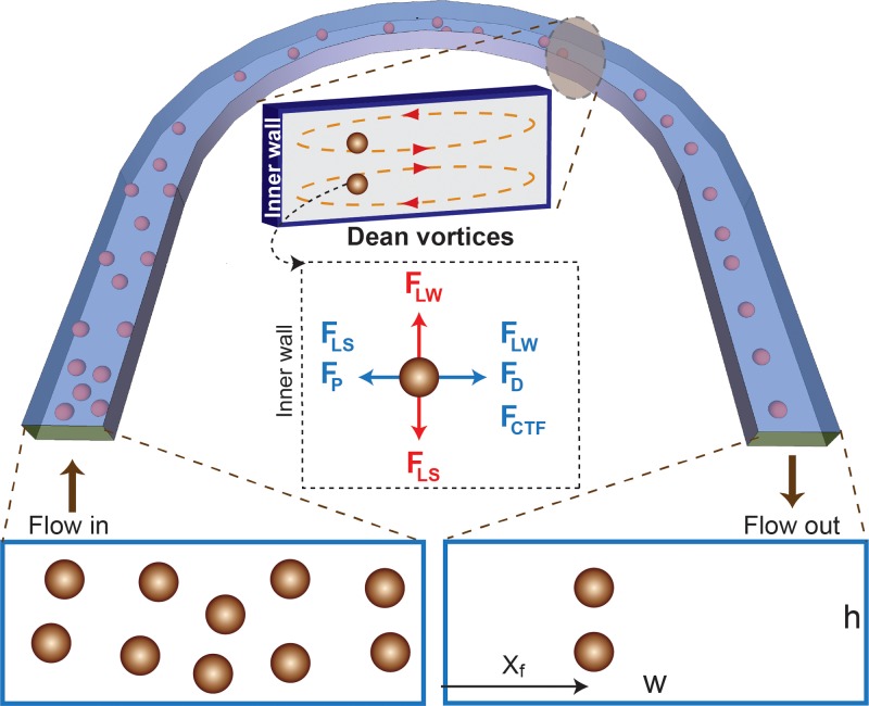
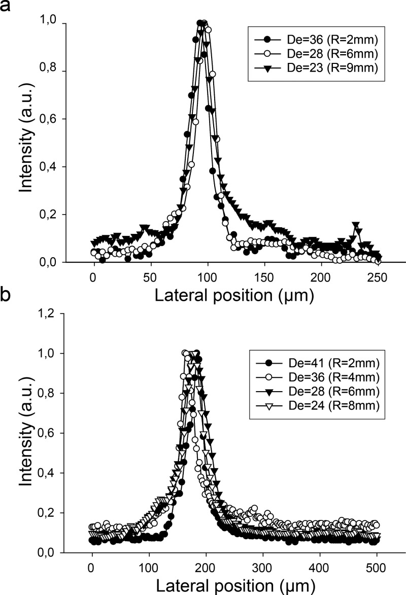
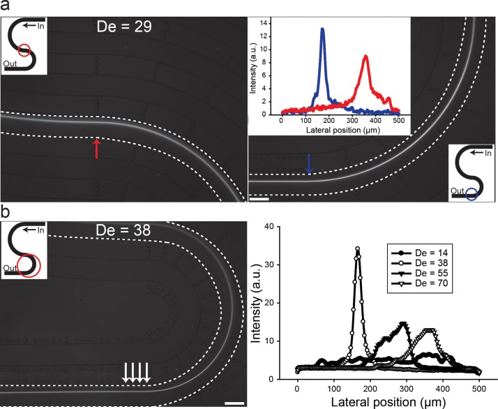
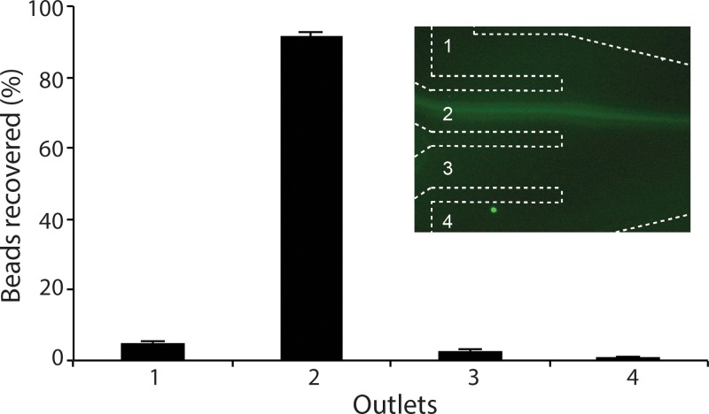
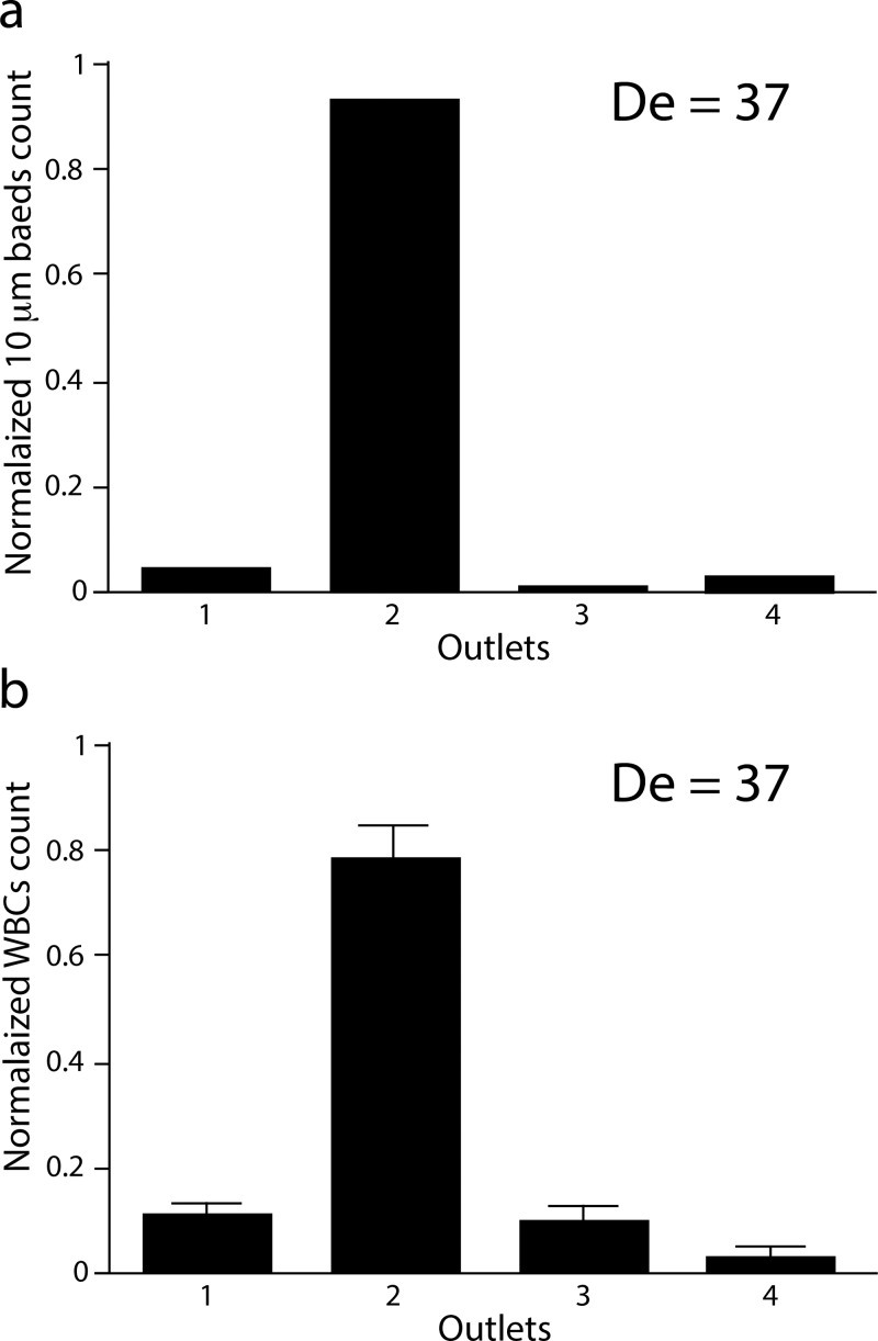
Passive particle focusing based on inertial microfluidics was recently introduced as a high-throughput alternative to active focusing methods that require an external force field to manipulate particles. In inertial microfluidics, dominant inertial forces cause particles to move across streamlines and occupy equilibrium positions along the faces of walls in flows through straight micro channels. In this study, we systematically analyzed the addition of secondary Dean forces by introducing curvature and show how randomly distributed particles entering a simple u-shaped curved channel are focused to a fixed lateral position exiting the curvature. We found the lateral particle focusing position to be fixed and largely independent of radius of curvature and whether particles entering the curvature are pre-focused (at equilibrium) or randomly distributed. Unlike focusing in straight channels, where focusing typically is limited to channel cross-sections in the range of particle size to create single focusing point, we report here particle focusing in a large cross-section area (channel aspect ratio 1:10). Furthermore, we describe a simple u-shaped curved channel, with single inlet and four outlets, for filtration applications. We demonstrate continuous focusing and filtration of 10 μm particles (with >90% filtration efficiency) from a suspension mixture at throughputs several orders of magnitude higher than flow through straight channels (volume flow rate of 4.25 ml/min). Finally, as an example of high throughput cell processing application, white blood cells were continuously processed with a filtration efficiency of 78% with maintained high viability. We expect the study will aid in the fundamental understanding of flow through curved channels and open the door for the development of a whole set of bio-analytical applications.


Figures

FIG. 1.
FIG. 1.
Schematic illustration of particle focusing in flow through curved channels. Randomly distributed particles are first affected by dominant lift forces in the straight channel. In this section, the particles start to focus vertically along the height of the channel. When the particles enter the curvature, counter rotating Dean vortices will force the particles to occupy a single lateral focusing point (xf) when exiting the curvature. Inset: Cross-section of the channel showing the presence of Dean vortices and how the dominant forces acting on a particle forcing it to focus in a distinct lateral position exiting the curved channel. Among the lift forces in flow through low aspect ratio, the vertical lift forces dominate and will tend to focus particles vertically on top and bottom while the Dean forces then move participles towards the lateral focusing position.
FIG. 2.
FIG. 2.
Computational analysis of the flow through curved channel. (A) Velocity profile of the transverse Dean flow at De = 36 for channel aspect ratio of 1:5 (h = 50 μm and w = 250 μm) and radius of curvature of 2 mm. The arrows indicate the magnitude and direction of the flow. (B) The influence of the lateral forces acting on a 10 μm particle due to curvature. The figure shows the secondary forces along the 50 μm channel height from the horizontal mid-plane to top (0 → H/2) at the lateral centre position (x = w/2), with the positive sign indicating direction towards the outer wall and negative sign towards inner wall. The centrifugal force (F_cft) directed towards the outer wall and is relatively small irrespective of De. The average Dean drag to pressure forces is about 4:1 for De = 36, and increases for De = 60. Note the Dean drag is directed towards the outer wall at the channel midpoint and changes sign as it approaches the channel top, while the pressure force is unidirectional toward the inner wall and constant.
FIG. 3.
FIG. 3.
Flow through curved u-shaped channel. (a) and (b) Fluorescence image of 10 μm particle flowing through the 180° u-shaped channel with channel widths 250 μm (a) and 500 μm (b). The radius of curvature, r, was 2 mm in both cases. (c) and (d) Cross-sectional intensity of the particles at the entrance and exiting points (see arrows in Figs. 2(a) and 2(b)) for channel widths 250 μm (c) and 500 μm (d) over a range of flow rates. Scale bar: 1 mm.
FIG. 4.
FIG. 4.
Fluorescence image of 10 μm particle flowing through the u-shaped channel at different flow rates. The radius of curvature, r, was 1.5 mm and the channel width 500 μm. Particles start to move laterally when entering the curved section, in a motion that follows the Dean vortices.
FIG. 5.
FIG. 5.
Cross-sectional intensity of 10 μm particles at the exiting points of the curved section for channel widths 250 μm (a) and 500 μm (b) over a range of radius of curvature. The lateral focusing position was fixed and independent of radius of curvature.
FIG. 6.
FIG. 6.
Summary of flow through “s-shaped” double curved channels. (a) Particles, pre-focused in the first curvature of the s-shaped channel (left panel), are maintained focused exiting the second curvature (right panel) with radius of curvature of 4 mm. Inset (right panel), the cross section intensities of particles entering and exiting the second curvature (red and blue arrow) is shown. (b) Intensity of particles flowing through the second curvature with radius of curvature of 2 mm (right panel) and average intensity of the area marked with arrows (left panel). The lateral focusing position was fixed (see Fig. 3(b) for comparison). Scale bar: 500 μm.
FIG. 7.
FIG. 7.
Ultra high-throughput filtration. 10 μm particles are successfully focused and filtered through outlet two (see inset) at flow rate of 4.25 ml/min. The filtration efficiency was 92%.
FIG. 8.
FIG. 8.
Filtration of leukocytes. (a) 10 μm particles focused and filtered through the u-shaped device. The filtration efficiency, defined as fraction of the particles recovered through outlet 2, was 96%. (b) Filtration of leukocytes. The filtration efficiency was 78% (n = 3). The flow rate was 2.2 ml/min (De = 37) in both cases.

References

    1. Kang K. H., Kang Y., Xuan X., and Li D., Electrophoresis 27, 694 (2006).10.1002/elps.200500558 - DOI - PubMed
    1. Pamme N. and Manz A., Anal. Chem. 76, 7250 (2004).10.1021/ac049183o - DOI - PubMed
    1. Petersson F., Nilsson A., Jönsson H., and Laurell T., Anal. Chem. 77, 1216 (2005).10.1021/ac048394q - DOI - PubMed
    1. MacDonald M. P., Spalding G. C., and Dholakia K., Nature 426, 421 (2003).10.1038/nature02144 - DOI - PubMed
    1. Zhu L., Zhang Q., Feng H., Ang S., Chau F. S., and Liu W.-T., Lab Chip 4, 337 (2004).10.1039/b401834f - DOI - PubMed