. 2015 May 1;523(7):997-1037.
doi: 10.1002/cne.23705. Epub 2014 Dec 16.

Neuroarchitecture and neuroanatomy of the Drosophila central complex: A GAL4-based dissection of protocerebral bridge neurons and circuits

Affiliations

Neuroarchitecture and neuroanatomy of the Drosophila central complex: A GAL4-based dissection of protocerebral bridge neurons and circuits

Tanya Wolff et al. J Comp Neurol. .

Abstract

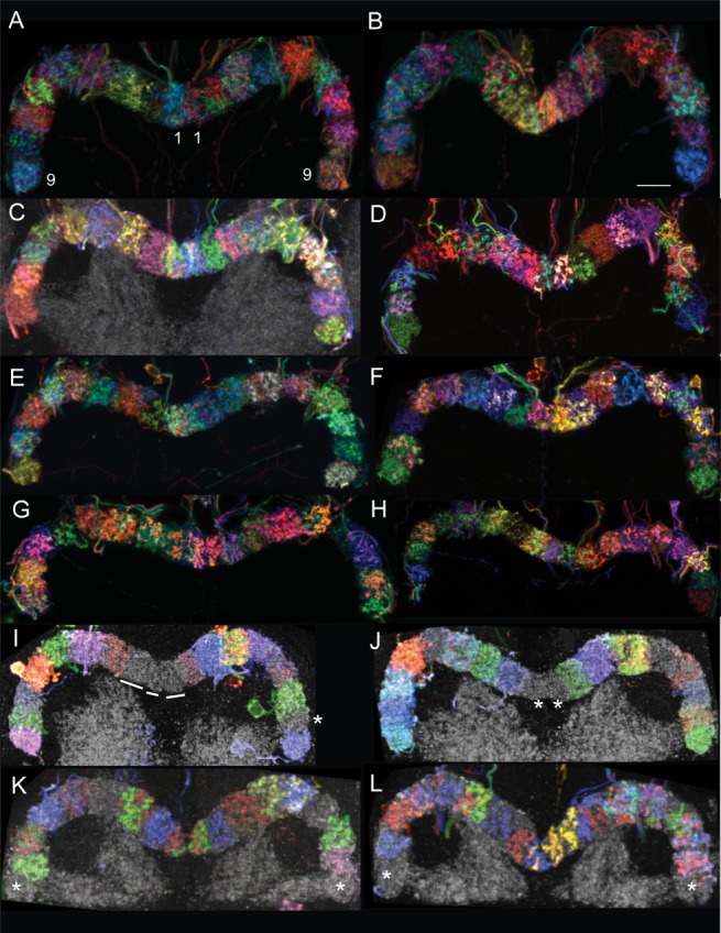
Insects exhibit an elaborate repertoire of behaviors in response to environmental stimuli. The central complex plays a key role in combining various modalities of sensory information with an insect's internal state and past experience to select appropriate responses. Progress has been made in understanding the broad spectrum of outputs from the central complex neuropils and circuits involved in numerous behaviors. Many resident neurons have also been identified. However, the specific roles of these intricate structures and the functional connections between them remain largely obscure. Significant gains rely on obtaining a comprehensive catalog of the neurons and associated GAL4 lines that arborize within these brain regions, and on mapping neuronal pathways connecting these structures. To this end, small populations of neurons in the Drosophila melanogaster central complex were stochastically labeled using the multicolor flip-out technique and a catalog was created of the neurons, their morphologies, trajectories, relative arrangements, and corresponding GAL4 lines. This report focuses on one structure of the central complex, the protocerebral bridge, and identifies just 17 morphologically distinct cell types that arborize in this structure. This work also provides new insights into the anatomical structure of the four components of the central complex and its accessory neuropils. Most strikingly, we found that the protocerebral bridge contains 18 glomeruli, not 16, as previously believed. Revised wiring diagrams that take into account this updated architectural design are presented. This updated map of the Drosophila central complex will facilitate a deeper behavioral and physiological dissection of this sophisticated set of structures.

Keywords: AB_1549585; AB_1625981; AB_528108; AB_915420; Drosophila brain; MCFO; ellipsoid body; fan-shaped body; glomerulus; nodulus.


Figures

Figure 1
Figure 1
Central complex. A: The central complex straddles the midline in the central brain (gray). Its four components are the protocerebral bridge (solid purple fill; posterior), fan-shaped body (green), ellipsoid body (orange; anterior); and noduli (solid blue fill). Accessory neuropils that are arborized by PB neurons include the crepine (CRE, transparent blue), rubus (RUB, yellow), gall (GA, red), and lateral accessory lobe (LAL, transparent purple). Posterior (B), sagittal (C; anterior to the right), and dorsal (D) views of the central complex. Images A–D were generated using Fluorender (Wan et al., ,). The four components of the central complex are shown immunolabeled with anti-nc82: (E) PB, (F) FB, (G) EB, and (H) NO. Asterisks in F highlight the layers that can be distinguished by differences in synaptic density, as measured by intensity of nc82 signal. Dorsal is up. Scale bars = 20 μm in A–D; 10 μm in E–G; 11 μm in H.
Figure 2
Figure 2
Nomenclature design. A: This generic schematic illustrates the nomenclature system. Three neuropils are shown. Neuropil 1, the first neuropil in a neuron's "name," is the neuropil closest to the cell body. The subdomains (abbreviated sd in the figure) are included in the neuron's name to define the subregion/s of the neuropils in which the cell type arborizes. For example, there are several distinct volumes in the EB, so the volume that is specific to a given cell type is included in the name. The third component of a cell's name is the predominant morphology of its arbors, abbreviated as either "s" for spines, or "b" for boutons. B,C: Two neurons are shown, accompanied by schematics to illustrate the cells' locations in the central complex, and by the neuron's name, annotated to illustrate how the name is derived. Letters that are used in the neuron names are highlighted in color. Ovals in the schematics represent the cell bodies, solid and hatched fills denote spine and bouton arbor morphologies, respectively. PB: protocerebral bridge; GA: gall; EB: ellipsoid body; cb: cell body; s: spines; b: boutons; FB: fan-shaped body; RUB: rubus.
Figure 3
Figure 3
Protocerebral bridge neuron catalog. Confocal images of all neurons with arbors in the PB that were identified in this study are shown. Each image is accompanied by a sketch that illustrates the neuropils in which the neuron arborizes. A: This schematic illustrates all neuropils that are arborized by the PB neurons described here, except the inferior bridge (IB) and superior posterior slope (SPS), which were omitted to simplify the schematic. The IB and SPS are shown in Ito et al., 2014. The schematic illustrates the current understanding of the subvolumes that constitute each of the neuropils shown, which is derived from work presented here. The neuropils were traced from a single focal plane of nc82-immunolabeled specimens, so they reflect the approximate shapes of their respective brain regions. The layout and relative sizes of the neuropils were modified to accommodate the two dimensionality of the schematic. The color scheme was chosen to best separate adjacent volumes and is not coordinated with volumes of similar color within this schematic, nor with any neurons or figures in the text. PB: protocerebral bridge. Numbers 1–9 in the PB identify each of the glomeruli of this neuropil. FB: fan-shaped body. Layers 1–9 of the FB are indicated. The relative widths of each layer are accurate for the focal plane shown. The irregular line that demarcates layer 4 from layer 5 is intended to illustrate the gaps in nc82 label in this region. The serrated ventral boundary of layer 1 depicts the seven teeth of this layer, as described below. The gall comprises three regions: the gall tip (GT), dorsal gall (DG), and ventral gall (VG). LAL: lateral accessory lobe. EB: ellipsoid body. CRE: crepine. RUB: rubus. NO1: dorsal nodulus. NO2D: dorsal subcompartment of medial nodulus. NO2V: ventral subcompartment of medial nodulus. NO3: ventral nodulus; individual subcompartments of this neuropil are not indicated in the schematic. B–U: Confocal images and sketches of neurons drawn on the template shown in A. Neuropils that are arborized by the neurons are highlighted in black, whereas regions that are not populated by a given neuron are shadowed in gray. In the sketches, spiny arbors are drawn as random scribbles and boutons are illustrated as dots. B: PBG2–9.s-FBℓ1.b-NO3P.b. C: PBG2–9.s-FBℓ1.b-NO3M.b. D: PBG2–9.s-FBℓ2.b-NO3A.b. E: PBG2–9.s-FBℓ3.b-NO2D.b. To more accurately depict the morphology of the arbor in layer 3 of the FB, it is shown extending into layer 4 in the drawing although in reality, the arbor is confined to layer 3. F: PBG2–9.s-FBℓ3.b-NO2V.b. The sense of depth conveyed by the maximum intensity projection of the confocal image is not conveyed in the 2-dimensional drawing. Consequently, the morphology of the NO2V arbor appears different in the sketch compared to the confocal image. G: PBG2–9.s-EBt.b-NO1.b.
Figure 4
Figure 4
The protocerebral bridge comprises 18 glomeruli. MCFO-labeled protocerebral bridge neurons highlight individual glomeruli in distinct colors. The PB is also immunolabeled with nc82, so glomeruli not containing stochastically labeled cells are gray (see lines and asterisks). The protocerebral bridges of both female (C,D,F–L) and male (A,B,E) brains each have 18 glomeruli. Brains from three GAL4 lines are shown, although the presence of 18 glomeruli is universal among all lines. A–H: [R33A12], a mixture of PBG1–8.s-EBt.b-D/Vgall.b and PBG1–8.b-EBw.s-D/Vgall.b neurons; I,J: [R37F06], PBG2–9.s-EBt.b-NO1.b neurons; K,L: [R60D05], PBG1–8.b-EBw.s-D/Vgall.b neurons; K: see also Movie 1; L: see also Movie 2. Movies 1 and 2: Each movie shows a different PB with MCFO-labeled cells in the glomeruli. Between zero and two cells arborize in each glomerulus. Numbers identify each glomerulus and are color-coded according to the color of the cells that arborize in the corresponding glomeruli. Scale bar = 8 μm.
Figure 5
Figure 5
Layers of the FB. A: nc82-labeled adult FB. Asterisks identify layers discriminated by their synaptic density and distribution. B–E: MCFO-labeled fan-shaped bodies. B: Layer 9 is the "cap" of the FB. A local interneuron that arborizes in two layers of the FB (left inset) terminates at sites presumed to be presynaptic at the top of the FB. It does not fill the entire cap (right inset, arrow); this unfilled tip may define yet another, more dorsal, layer. C: A red, large-field neuron arborizes in the FB between FBℓ1 and FBℓ2 (layer 1d/2v). This neuron defines either a separate layer or a sublayer of either FBℓ1 or FBℓ2. Layer 3 is not evident at this angle of orientation. D: MCFO of a brain from GAL4 line [R34E11] reveals a distinct, unlabeled layer 3 between layers 2 and 4, both of which are clearly delineated by MCFO-labeled neurons. E1: The dorsal layers 9, 8, and 6 are highlighted by MCFO-labeled neurons; layer 7 appears as a gap labeled only with nc82. A large-field neuron arborizes throughout only the dorsal half of layer 6 (the ventral half is labeled with nc82, as shown in E2), perhaps defining it as a separate layer. The exclusion of the red layer 8 neuron from layer 9 and the green layer 9 neuron from layer 8 substantiates the assignment of these domains as distinct layers [GAL4 line R34H05]. E2: High-magnification view of E1 with nc82 label included. Layers 5 and 7 are evident, as is the synapse-dense ventral region of layer 6 from which the green neuron in E1 is excluded. E3: Sagittal view of brain shown in panel E1 highlights the dorsal position of the green neuron in layer 6.
Figure 6
Figure 6
Projection pattern between the PB and FBℓ1. A: nc82-labeled FB. This focal plane illustrates the medial and two neighboring teeth on each side of the midline. B: Distinction between the lateralmost and cryptic teeth of FBℓ1. The green arbor, consisting of boutons, is in the lateralmost tooth and originates from a PBG2–9.s-FBℓ1.b-NO3P.b neuron in G3L. The blue, bouton-rich arbor is in the cryptic tooth and arises from a PBG2–9.s-FBℓ1.b-NO3P.b neuron that arborizes in G2L [R65B12]. These FBℓ1 domains are also illustrated in Movie 3. C: PBG2–9.s-FBℓ1.b-NO3P.b neuron. D: Schematic representation of PB:FBℓ1 circuitry of the PBG2–9.s-FBℓ1.b-NO3P.b neuron. The glomeruli in which this neuron arborizes (G2–G9), the specific FB teeth they target and the lines connecting them, are similarly colored to more easily follow the projection pattern for this cell type. The numbers beneath each tooth of the FB refer to the glomeruli from which they receive input, and "i" and "c" refer to ipsilateral and contralateral. The arbors from pairs of neurons that target the same teeth intermingle within the FB domains, although for clarity the colors are separated in the schematic. At the second junction, between the FB and NO, the primary neurites from G9–G6 cross the midline to arborize in the contralateral noduli (not shown). The remaining projections, from G5–G2, have already crossed the midline and therefore do not cross the midline again. E: Two examples of FBℓl.b-NO3P.s-LAL.s.b-cre.s.b neurons [R44C06] highlight FBℓ1 teeth with tufts of boutons. Each tuft is located in a separate tooth with the exception of the central tooth, which houses two tufts; asterisks identify the tufts. A clear distinction between the left, lateral two teeth in the red example (right panel) is obscured in this focal plane, although the individual neurites leading to the tufts are evident and reveal the separate arbors. The two ventral tufts in both the green (left) and red (right) neurons that are not marked with asterisks arborize in the noduli. Movie 3 shows NO1, NO2 and a small portion of the FB. The green cell originates from G2L in the PB and arborizes in the cryptic tooth of the FB (labeled C). The blue boutons are in the most lateral tooth and course from G9R in the PB. The more medial green arbor (not labeled) arises from G8R. Left scale bar = 8 μm, right scale bar = 10 μm in E.
Figure 7
Figure 7
EB shells and nubbin. A: Anterior (cyan and yellow) and medial (green) shells are highlighted with MCFO-labeled neurons whereas the posterior shell lacks signal (gray, nc82). Left panel is an off-axis frontal view to provide a sense of depth of the shells. Right panel is a sagittal view [R30F05]. B: Anterior (orange) and posterior (red) shells are highlighted by ring neurons; medial layer is unlabeled. Left panel is frontal view, right panel is sagittal view [R13D05]. C: Sagittal views of two EBs are shown. The EB arbors of tile cells, in this case PBG1–8.s-EBt.b-D/Vgall.b cells (green, top; yellow, bottom), fill just the posterior shell, whereas the PBG1–8.b-EBw.s-D/Vgall.b cell (red, top and bottom) fills both the posterior and medial shells. Arrows identify the anterior shells, which lack labeled arbors. D: Two EBs are shown in sagittal view. The EB arbor of EBw.AMP.s-Dga-s.b cells (blue and green) fills all three shells: posterior, medial. and anterior. Arrows again identify the anterior shell. E: Frontal and side views of a BU.s-EBnub.b neuron. The EB arbor is restricted to the anterior protuberance of the EB [R41G11]. This cell is not a PB neuron, but is used to show the morphology of the nubbin. Scale bar = 19 μm in E. See also Movie 4. Anterior is to the right for all side views. Movie 4: The red arbor of a BU.s-EBnub.b neuron fills the nubbin subregion of the EB.
Figure 8
Figure 8
Wedge and tile cells. A: PBG1–8.b-EBw.s-Vgall.b. B: PB G1–8.s-EBt.b-Dgall.b. C1: PBG1–8.s-EBt.b-Vgall.b (left) and PBG1–8.b-EBw.s-Vgall.b (right) cells. C2: Same cells as shown in C1 with nc82 for reference. PB in left panel; EB and gall in center panel; dorsal gall, right panel. D1: PBG2–9.s-EBt.b-NO1.b cell. D2: Same cell as shown in D1 with nc82 for reference. PB shown in left panel and EB and NO1 in right panel. Note that the profile of the FB is replaced by that of the EB in more anterior focal planes. In the plane shown here, the FB is just beginning to give way to the EB, so the EB arbor appears to reside in the FB. PB: protocerebral bridge; EB: ellipsoid body; GA: gall; NO: nodulus.
Figure 9
Figure 9
The EB comprises 16 wedges and 32 demi-wedges. A1–A3: Confocal images and schematics of MCFO-labeled protocerebral bridges and corresponding ellipsoid bodies from three densely labeled brains. Cell type: PBG1–8.b-EBw.s-D/Vgall.b. Colors used in the schematics do not necessarily correspond to the colors in the confocal images because of color redundancy in the data panels. Two of the 41 labeled glomeruli shown in these three brains had three labeled cells each: G4R and G8R in A1. Note that in A1, the green cell in G4R transitions to yellow in the EB due to ramping of the laser power during imaging. To minimize confusion, this cell is green in the schematic in both the PB and EB. Brains shown in A1 and A3 are from line [R60D05]; brain in A2 is from [R33A12]. B,C: Demi-wedges are illustrated in these high magnification confocal images of small portions of two ellipsoid bodies. Two cells are labeled in the glomeruli (insets) corresponding to the wedges shown. For each example, three panels are shown. The first shows both cells (or both colors), followed by each color shown separately to illustrate the gap, or demi-wedge, occupied by the partner cell. The asterisks identify the two demi-wedges corresponding to a single wedge. Note that while there is some overlap between these EB arbors, there is a clear distinction between the two arbors that originate from the same glomerulus. B: An enlargement of a portion of the EB shown in A1; the region of interest is G4L, which contains a red and blue cell, shown in inset. See also Movie 5. C: The wedge labeled with blue and red arbors (9:00, red and yellow asterisks) exemplifies an instance in which the arbors from two cells from the same glomerulus both occupy the entire wedge. These cells arborize apparently presynaptically in G3R. The blue and green cells occupy adjacent demi-wedges of a single wedge and have their PB bouton arbors in G8L (inset). Brain shown in C is from line [R60D05] and is the same brain shown in Movie 6. Movie 5 The red and blue cells highlighted here with asterisks occupy adjacent demi-wedges of the same wedge. Cells both arborize in G4L of the PB (shown in Fig. 9). The gaps that appear when the red and blue channels are turned off are the demi-wedges. Movie 6 illustrates two cells with bouton-type arbors in a single glomerulus, G8L (labeled G8), and postsynaptically in adjacent demi-wedges in the EB. One cell is green, the second is blue; they arborize in the EB at ∼8:00. The densest regions of the spiny arbors in the demi-wedges, the spines (as in backbones), are marked with the paired blue and green asterisks. There is a second green cell that arborizes at about 11:00 in the EB that does not arise from G8L (yellow asterisk). A second pair of cells, one red and one blue (paired red and blue asterisks), projects from G3R (glomerulus not shown). These cells arborize in the EB at 10:00 and overlap extensively in either the same wedge or demi-wedge. The Z series of the blue cell illustrates the projection of the cell (orange arrow identifies primary neurite) that arborizes in G8 to the lower blue arbor in the EB (orange asterisk). Similarly, the Z series of the green cell shows the projection from G8 to the green demi-wedge in the EB (purple asterisk), although this path is more difficult to follow.
Figure 10
Figure 10
Arbors in EB wedge and tile domains are not confined within strict boundaries. A: Spiny arbors of three PBG1–8.b-EBw.s-D/Vgall.b cells in three adjacent EB wedges are shown: The central green cell's arbor is bordered dorsally by the red cell and ventrally by the blue cell. The spiny arbors of PBG1–8.b-EBw.s-D/Vgall.b cells in wedge domains are dense centrally, resembling a backbone, and become increasingly sparse peripherally. The lines identify the approximate extreme lateral limits of spiny arbors from adjacent wedges. While there is variability in the extent of the domains of arborizations, arbors do not extend beyond the adjacent EB domain. The degree of overlap of arbors in neighboring wedges is evident in the examples shown in which color channels were separated to illustrate the individual neurons. B: Arbors consisting of boutons also extend into neighboring tile domains, illustrated in these five examples. Asterisks identify boutons from PBG1–8.s-EBt.b-D/Vgall.b cells that intrude into neighboring tile domains. C: Schematics illustrating the extension of spiny (top) and bouton (bottom) arbors into adjacent domains.
Figure 11
Figure 11
The EB comprises eight tiles. A–D: MCFO-labeled protocerebral bridges and corresponding ellipsoid bodies from four brains from line [R37F06]. The cell type labeled is PBG2–9.s-EBt.b-NO1.b; the noduli are not shown. The unlabeled gap in the center of the PB reflects the fact that this cell type does not arborize in G1. Note that the colors in the PB are not always preserved for a given cell in the EB due to laser adjustment (ramping) through a confocal stack. For example, in B the cell that arborizes in G2R is purple in the PB and blue in the EB. In this same brain, G9L is pink in the PB due to the presence of two labeled cells, one green and one blue (see inset of PB, in which the green and blue channels were independently toggled off to demonstrate the presence of the two neurons); the bouton arbors from these two cells are clearly blue and green in the EB. The eight tile volumes are evident in the EB; the glomeruli from which they originate are indicated next to each EB tile. In panel A, the EB is shown twice, the second time with the green channel turned off to reveal arbors that are obscured by the green channel (i.e., the red arbor from 4R).
Figure 12
Figure 12
Anatomy of subcompartments of the noduli. A: Frontal view of NO1 pairs illustrating the apparent subdivision of NO1 into medial and lateral halves. Noduli are from [R65B12] (A1,A2) and [R12D09] (A3,A4). B: Frontal (B1,B3) and sagittal (B2) views of nc82-labeled (B1,B2) and MCFO-labeled noduli (B3) illustrating the subcompartments of the noduli. B3 is from line [R65B12]. C: Frontal (C1) and sagittal (C2,C3) views of subcompartments of noduli. C2 shows the left set of noduli, C3 shows the right noduli of a brain from line [R34H05]. D: Sagittal views showing labeled neurons in NO2V from line [R37F06]. Black asterisk marks NO1. E–G: Sagittal views of MCFO-labeled subcompartments of noduli from [R65B12]. (Note that in panel E1 the brighter label in NO3P is bleed-through from the neuron labeled in E2.) F,G: The distinction between the three subcompartments of NO3 is illustrated using the MCFO technique. See accompanying Movie 7. Anterior is to the right for all sagittal views. Movie 7: NO1, the two subcompartments of NO2 and the three subcompartments of NO3 are clearly distinguished in this movie. Colored labels correspond to the colors of the cells that fill various compartments. NO1, NO2V, and NO3P are labeled only with nc82.
Figure 13
Figure 13
Gall subcompartments. A: The three subcompartments of the gall are delineated by cells labeled with the MCFO technique. Subcompartments are labeled in each panel. T: gall tip. D: dorsal gall. V: ventral gall. The gall tip is identified by PBG9.s-EB.P.s-ga-t.b; the D and V gall are identified by PBG1–8.b-EBw.s-D/Vgall.b and PBG1–8.s-EBt.b-D/Vgall.b cells. B1–B3: Adjacent glomeruli (top) and corresponding galls (bottom) containing cells labeled using MCFO. nc82 is gray channel in all panels. B1,B2: PBG1–8.b-EBw.s-D/Vgall.b (from line [R60D05]) and B3) PBG1–8.s-EBt.b-D/Vgall.b cells (from line [R33A12]). B1: Orange cell is in G7 and arborizes in the dorsal gall; blue cell is in G6 and arborizes in the ventral gall. B2: Blue cell is in G8 and the ventral gall; red cell is in G7 and the dorsal gall. The apparent gap between the red and blue cells in the glomeruli is not an intervening glomerulus, but is a consequence of both a slightly buckled PB between G7/G8 and the fact that the blue arbor does not completely fill G8. B3: Red cell is in G4 (top) and the ventral gall (middle, frontal view), blue cell arborizes in G3 (top) and the dorsal gall (middle). Lower panel is a side view of the gall to illustrate that the apparent overlap of the red and blue arbors in the frontal view is a consequence of the fact that the D and V domains are staggered on the D/V axis.
Figure 14
Figure 14
Connectivity between the PB and EB tiles. Schematics illustrating the projection patterns between the PB and EB tiles for two cell types, each of which targets a different subset of glomeruli. Schematics were derived from MCFO-labeled brains. Top: PB, middle: EB; bottom: filleted EB, as described in text. Glomeruli and their target EB volumes are color-matched. The numbers below the PB identify each of the glomeruli, whereas the black text around the EB denotes coordinates of an analog clock for use as reference. A: This wiring scheme represents the cell type PBG2–9.s-EBt.b-NO1.b, which does not arborize in G1 (gray in PB). Two cells, one ipsilateral and one contralateral, arborize in each tile. The three distal glomeruli project ipsilaterally in the EB, G6 and G2 occupy the midline volumes (the zenith and nadir, respectively), and G3–G5 project contralaterally in the EB. This linear projection pattern is readily seen by comparing the PB to the filleted EB. B: Wiring scheme for PBG1–8.s-EBt.b-D/Vgall.b cells, which do not arborize in G9 (gray in PB; [R33A12]). The same basic circuitry scheme illustrated in A applies to this cell type, but the ipsilateral/contralateral split is shifted laterally by one glomerulus since EBt.b-D/Vgall.b cells do not arborize in G9 but do arborize in G1. Therefore, the three most lateral glomeruli project ipsilaterally, G5 and G1 arborize in the midline volumes (the apex and antapex, respectively), and G4–G2 project to the contralateral EB. PBG1–8.s-EBt.b-D/Vgall.b cells in even-numbered glomeruli project to the ventral gall whereas odd-numbered glomeruli project to the dorsal gall (labeled D and V above each glomerulus of the PB).
Figure 15
Figure 15
Connectivity between the PB and EB wedges. This schematic was constructed based on MCFO-labeled PBG1–8.b-EBw.s-D/Vgall.b cells, which do not project to G9 (gray in PB). Schematics of the PB, EB, and filleted EB are shown. Between zero and three cells are labeled in each glomerulus. Alphanumeric labels on the EB and filleted EB indicate the glomeruli from which cells project to each volume; the number refers to the glomerulus number, R is shorthand for right, and L for left. Alternating wedges are filled with gray or white and demi-wedges are indicated by a solid line that divides each wedge. Various combinations of wedge and demi-wedge arbor fills are illustrated. For example, G8R illustrates an example with three labeled cells; the purple and yellow occupy one demi-segment in the EB, the green occupies the other demi-segment of the same wedge. G1R has two labeled cells, both of which fill the entire EB wedge that corresponds to G1R. G5L and G3R each have just one labeled cell, but G3R fills its entire corresponding wedge, whereas G5L fills just a demi-wedge. As with PBG1–8.s-EBt.b-D/Vgall.b cells (above), PBG1–8.b-EBw.s-D/Vgall.b cells project to either the dorsal or ventral gall in the same glomerulus-specific fashion: even-numbered glomeruli project to the ventral gall whereas odd-numbered glomeruli project to the dorsal gall, as indicated by the D and V designations above the PB.
Figure 16
Figure 16
Connectivity between the FB and noduli. A: The schematic illustrates the circuits between three layers of the FB—ℓ1, ℓ2, and ℓ3—and the subcompartments of the noduli to which the cells from these layers project. For clarity in illustrating the FB-NO connections, since the three NO3 subcompartments are not visible in a frontal view, noduli are shown in the schematic in a sagittal view (as in Fig. 12E2); inset of NO is frontal view. Arrows indicate projections from the PB. NO1 is not directly wired to the FB. B: PBG2–9.s-FBℓ2.b-NO3A.b [R34H05]. C: PBG2–9.s-FBℓ3.b-NO2D.b [R44C06]. D: PBG2–9.s-FBℓ3.b-NO2V [R37F06]. E: PBG2–9.s-FBℓ1.b-NO3M.b [R85H06]. Scale bars = 14 μm in B,E; 11 μm in C; 13 μm in D.
Figure 17
Figure 17
A segregated circuit connects the dorsal and ventral gall to distinct volumes in the EB and PB. Two cells, PB.s-EBt.b-D/Vgall.b and PB.b-EBw.s-D/Vgall.b, relay information between the PB, EB, and gall. Information is relayed from the even glomeruli to corresponding tiles in the EB (as described in Fig. 14) and to the ventral gall via the PB.s-EBt.b-Vgall.b cells (cell A). Similarly, information is relayed from the odd glomeruli to the odd-corresponding set of tiles in the EB (see also Fig. 14) and to the dorsal gall via the PB.s-EBt.b-Dgall.b cells (cell C). Information is transmitted from the EB to the PB and gall via the PB.b-EBw.s-D/Vgall.b cells. Cells in the wedges that correspond to the even glomeruli deliver information to the even glomeruli and to the ventral gall via the PB.b-EBw.s-Vgall.b cells (B) and from the odd-corresponding wedges to the odd glomeruli and dorsal gall via the PB.b-EBw.s-Dgall.b cells (D). Both cell types occasionally extend tendrils, skipping their adjacent neighbor to maintain the odd/even integrity of a cell. The green cell is an example of the cell type shown in D, where the primary bouton arbor is in G1 and a single bouton from the same cell extends to G3. The light blue cell is an example of the cell type shown in A with a primary arbor in G4 and secondary arbor in G6.
Figure 18
Figure 18
Unusual PB cell types. Confocal images of assorted atypical neuronal cell types. A: PBG2–9.b-IB.s-SPS.s neurons (from left to right: contralateral, green; ipsilateral, blue and red). The green bouton arbor occupies three glomeruli in the PB (asterisks). B: PB18.s.GxΔ7Gy.b neurons. This arbor is primarily spiny in morphology with two clusters of boutons spaced seven glomeruli apart [R34E11]. C: The morphology of the PBG6–8.s-G9.b arbors resembles boutons in G9 and spines in G6–8 [R18G01]; four neurons are shown. D–F: PBG1/2–9.b-SPSi.s cells. D1 and D2 are the same neuron, with and without the nc82 channel shown. E1: The left half of the PB is arborized by a pink example of PBG1/2–9.b-SPSi.s and the right half is arborized by two PBG1/2–9.b-SPSi.s cells, one orange and one blue. E2: A magnified portion of the right PB (boxed region in E1) is shown to illustrate the close proximity of the boutons from these two cells. F1: Each half of the PB is populated by two neurons. The close proximity of the boutons from two of these cells is shown (F2, [R33D11]). G: PBG9.s-EB.P.s-ga-t.b cells.
Figure 19
Figure 19
Three subtypes of neuron PBG1–7.s-FBℓ2.s-LAL.b-cre.b. Short, medium, and long LAL arbors for PBG1–7.s-FBℓ2.s-LAL.b-cre.b neurons are shown. Asterisks indicate where the "tails" of the arbors exit the LAL. A: Long (left, blue and red) and short (right, green) versions of the LAL tail. Both sides arborize dorsally in the crepine. B: Medium arbor (left, purple); note that the faint green arbor does exit the LAL but only three of its boutons lie outside the LAL. Both red and green arbors on the right are the long variety. Both left and right arbors also infiltrate the crepine [R11B11]. Scale bars = 10 μm in A; 12 μm in B.
Figure 20
Figure 20
Variants of the EBw.AMP.s-Dga-s.b cell. The EB.w.AMP.s-Dga-s.b cell seems prone to errors since two variants of the cell were seen multiple times. A: In one variant (EBw.AMP.s-Dga-s.b-EBw.A.s; [R38C04]), a second, sparse, spiny arbor projects to the anterior shell of the EB (asterisks). B: There is just one EB arbor in the "wild-type" cell (EBw.AMP.s-Dga-s.b; found in [R38B06][R38C04][R41G11]). C: In the second variant (PB.s-EBw.AMP.s-Dga-s.b; [R38B06]), a small spiny arbor projects to the PB (asterisks). Scale bars: blue cell, 14 μm; orange cell, 10 μm in A; yellow cell, 10 μm; blue cell 24 μm in B; orange cell, 6 μm; green cell 18 μm in C.
Figure 21
Figure 21
Horizontal fiber system cells and projections. The projection patterns of HFS cells differ from published accounts only for cells that arborize in G1 and G8, so only examples for these glomeruli are shown. A–D: PBG1–8.s-FBℓ3,4,5.s.b-rub.b cells. The PB arbor is sparse. It is likely that the FB arbor also has boutons in addition to the more obvious spines. Insets show glomeruli in which cells of interest arborize; nc82 highlights the bridge; spiny arbors are either green or blue. A: This cell arborizes in G8R (8), the ipsilateral FB (FB) and contralateral rubus (RUB). B: Two cells are labeled; one arborizes in G8L (8), the second in G7L (7). Both arborize in the ipsilateral FB (FB) and cross to the contralateral rubus (RUB). C: Two blue cells are labeled. One arborizes in G1L (1) and the second arborizes in G8R (8). The projection from G8R to the ipsilateral FB (right, FB 8) is evident. The primary neurite then courses from the FB to the contralateral rubus (8, RUB). The second blue cell arborizes in G1L (1), then courses to the ipsilateral FB (FB 1), and finally to the ipsilateral rubus (1, RUB) where it joins the rubus arbor from G8R. Left inset illustrates the G1L cell arbor in the PB; right inset shows the G8R cell arbor in the PB, with G9 situated just below and G7 just above the labeled glomerulus. D: G1L (inset and noted with a "1" in panel D) projects to the ipsilateral FB (FB) and ipsilateral rubus (RUB).
Figure 22
Figure 22
Horizontal fiber system wiring diagram. Schematic of the revised projection pattern of the cell that is the basis of the HFS, the PBG1–8.s-FBℓ3,4,5.s.b-rub.b cell. This cell does not arborize in G9. Top: PB; middle: FB (layers 1 through 5 are shown); circles: rubus; bottom: FB. The projections illustrated here differ in several key respects from the published HFS projection patterns: 1) Cells that arborize in G8 do cross the midline; they do not follow an ipsilateral projection; 2) Cells that arborize in G1 remain ipsilateral; they do not cross the midline; 3) G1, not G8, arbors occupy the most lateral column of the FB. Note that the arbors from G8–G6 remain ipsilateral in the FB and those from G4–G2 consistently project to the contralateral FB, whereas arbors from G5 occupy a more loosely demarcated geographic volume: They course to the midline, but can arborize on either the ipsilateral or contralateral side of the midline or on the midline. Nonetheless, G5 arbors always terminate in the contralateral rubus (dashed and solid yellow lines from G5 to FB to rubus). The composite outlined here was not constructed from densely labeled brains, as described for the PBG1–8.b-EBw.s-D/Vgall.b cell (Fig. 15), so not every cell was seen with direct relation to its nearest neighbors. One brain was documented to show the key spatial relationship between G1L and G8L in the FB; this relationship was confirmed in numerous other brains in which either G1 or G8 cells were labeled, as the most lateral two FB columns can be readily distinguished from one another. The relative positions of neighboring arbors in the FB were also confirmed (and in some cases determined) by comparing FB arbor positions in different brains. The relative positions, shown here, largely—but not completely—resemble the projection pattern for the PBG1–8.b-EBw.s-D/Vgall.b cell type.

References

    1. Baker DA, Beckingham KM, Armstrong JD. Functional dissection of the neural substrates for gravitaxic maze behavior in Drosophila melanogaster. J Comp Neurol. 2007;501:756–764. - PubMed
    1. Bausenwein B, Muller NR, Heisenberg M. Behavior-dependent activity labeling in the central complex of Drosophila during controlled visual stimulation. J Comp Neurol. 1994;340:255–268. - PubMed
    1. Bausenwein B, Wolf R, Heisenberg M. Genetic dissection of optomotor behavior in Drosophila melanogaster. Studies on wild-type and the mutant optomotor-blindH31. J Neurogenet. 1986;3:87–109. - PubMed
    1. Bender JA, Pollack AJ, Ritzmann RE. Neural activity in the central complex of the insect brain is linked to locomotor changes. Curr Biol. 2010;20:921–926. - PubMed
    1. Butcher NJ, Friedrich AB, Lu Z, Tanimoto H, Meinertzhagen IA. Different classes of input and output neurons reveal new features in microglomeruli of the adult Drosophila mushroom body calyx. J Comp Neurol. 2012;520:2185–2201. - PubMed

Publication types

LinkOut - more resources