

doi: 10.3390/s141121626.
Multispectral filter arrays: recent advances and practical implementation
Affiliations
- PMID: 25407904
- PMCID: PMC4279553
- DOI: 10.3390/s141121626
Item in Clipboard
Multispectral filter arrays: recent advances and practical implementation
Sensors (Basel).
.
Abstract
Thanks to some technical progress in interferencefilter design based on different technologies, we can finally successfully implement the concept of multispectral filter array-based sensors. This article provides the relevant state-of-the-art for multispectral imaging systems and presents the characteristics of the elements of our multispectral sensor as a case study. The spectral characteristics are based on two different spatial arrangements that distribute eight different bandpass filters in the visible and near-infrared area of the spectrum. We demonstrate that the system is viable and evaluate its performance through sensor spectral simulation.
Figures
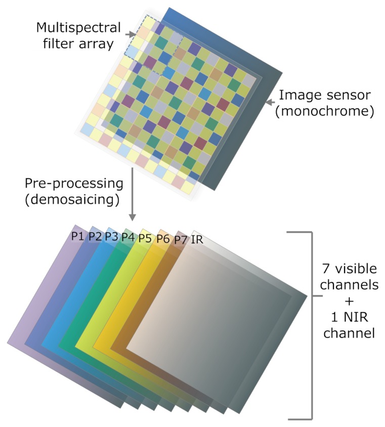
Global scheme of the multispectral imaging system. With the filter array technique, the filter is mounted on a common CMOS image sensor.
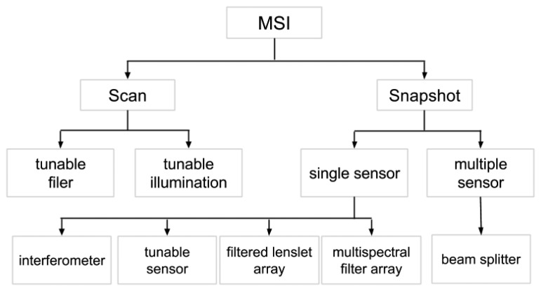
Classification tree of the main methods for multispectral capturing.

Schemes of the principles used by the techniques of filter wheel and liquid crystal tunable filters (LCTF). (a) Filter wheel with optical bandpass filters. Multispectral imaging is recorded by shifting the filters sequentially into the optical path; (b) Acousto-optical tunable filter principle. The acousto-optic effect is used to diffract and shift the frequency of light using sound waves.
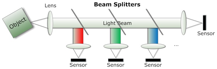
The design of a multi-spectral system. Three beam splitters with different wavelength ranges and three highly reflective mirrors.
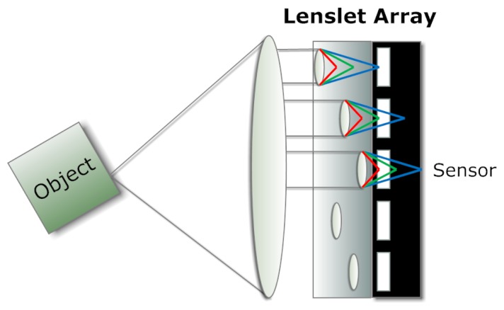
Example of a lenslet array, where the wavelengths are selected according to the distance between each lens and the corresponding photodetector.

The multispectral reconstruction capability is based on suitable biasing. Carriers are collected by the contact pairs from different depths, and each contact pair has its own spectral response.
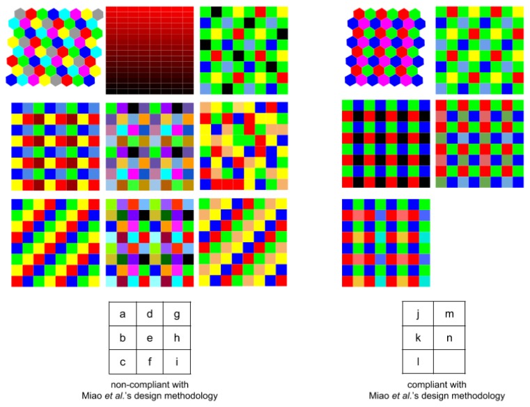
(a) Ramanath et al. [32]; (b) Brauers and Aach [47]; (c) Aggarwal and Majumbar [48]; (d) Wang et al. [50]; (e) Lu et al. [52]; (f) Sadeghipoor et al. [53]; (g) Kiku et al. [58]; (h) Aggarwal and Majumbar [59]; (i) Aggarwal and Majumbar [59]; (j) Ramanath et al. [32]; (k) Hershey and Zhang [49]; (l) Yasuma et al. [55]; (m) Monno et al. [56], Shrestha and Hardeberg [57].
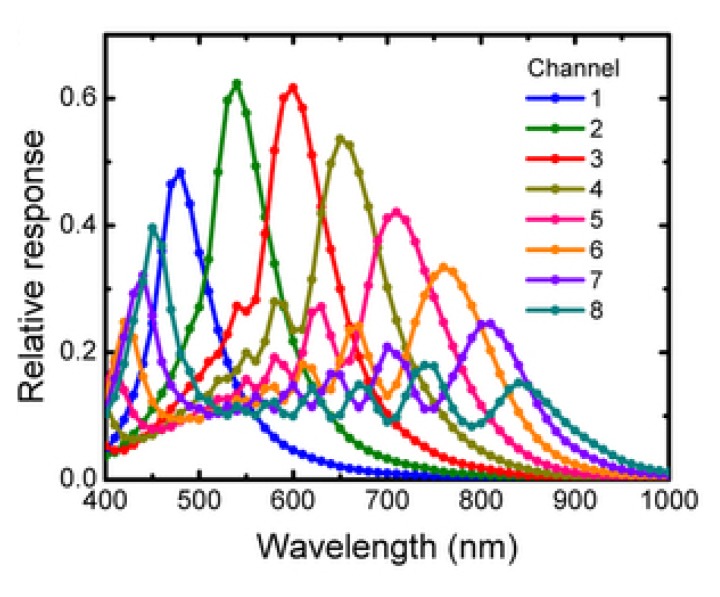
Relative response of multispectral imaging using vertical silicon nanowire photodetectors [77,78]. Reproduced here with their permission.
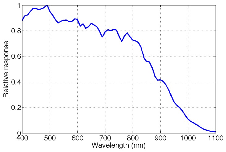
Relative response of the e2v EV76C661ABT sensor [88]. The measurements were done using the OL Series 750 Spectroradiometric Measurement System [89] with a tungsten lamp.
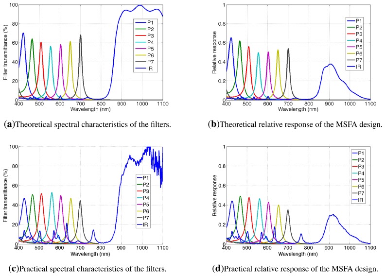
(a) Spectral characteristics of the filters. Channels {P1 – P7; IR} are labeled following the scheme of Figure 11; (b) Simulation of the relative actual response of the multispectral imaging system (sensor associated with filters). Measured data (c) and (d) highlight some spectral differences compared to simulation.
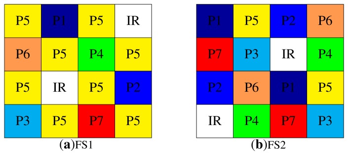
FS1 (a) and FS2 (b) are two different moxels. FS1 shows an ad hoc distribution with over-sampled channels (P5 and NIR), FS2 shows uniformly distributed samples as an instance of Miao et al.'s [44] binary tree algorithm. Refer to Figure 10c for the spectral characteristics of the filter channels.

One alignment matrix (a), in the top left corner of the filter array; (b) Each filter covers 4 × 4 pixels of the sensor.
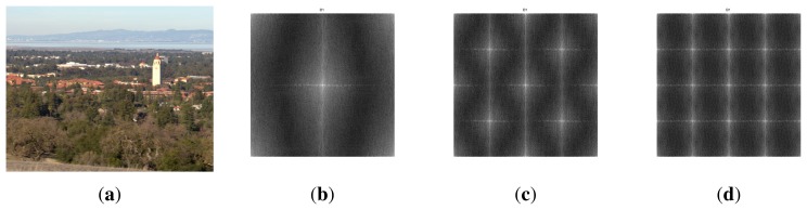
(a) The multispectral image by Skauli et al. [102] is used; (b,c,d) Log-magnitude representation of spatial arrangements for both FS1 and FS2. (a) Stanford image; (b) P5 over FS1; (c) IR over FS1 and P{1,2,3,4,5,6,7,IR} over FS2; (d) P{1,2,3,4,6,7} over FS1.

Overview of the hardware/software system integration, with a front view of the assembled camera without a lens (b); This camera architecture is used in order to test and characterize the sensors; (a) Our global system; (b) Zedboard + sensor daughter board.
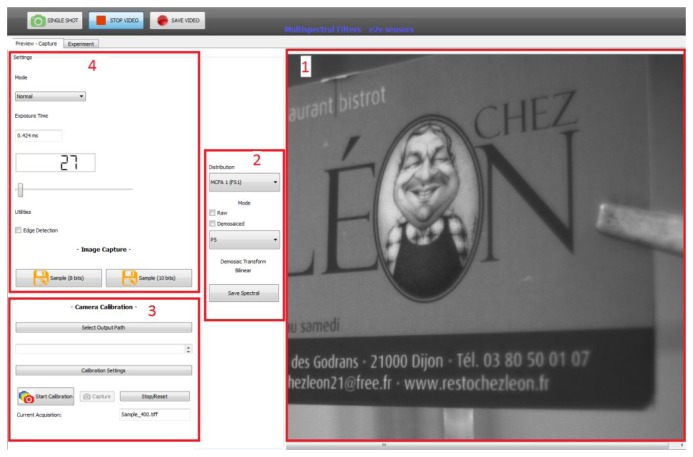
The control software. Application features: 1, video preview; 2, channel and filter selection; 3, characterization tool; 4, setting tools. A preview after bilinear demosaicing is a functionality of the application.
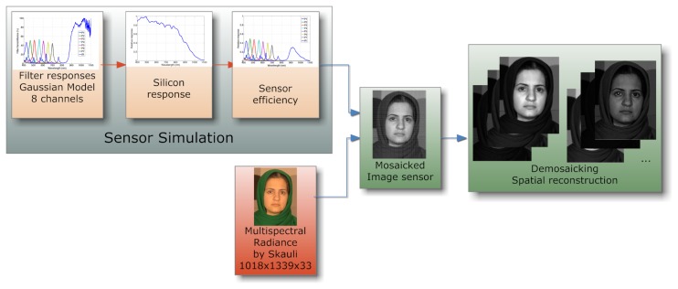
Simulation scheme of multispectral filters. The sensor system (photoreceptor and filters) is simulated using a particular illuminant and the silicon response of our sensor.
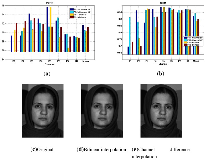
(a,b) Peak signal-to-noise ratio (PSNR) and structural similarity (SSIM) results of demosaicing simulation using the Skauli database [102]; (c) The ground truth image through the FS1 arrangement (P4 channel); (d) the image demosaiced by the bilinear interpolation and (e) the image demosaiced by the channel difference interpolation are shown.
References
-
- Stevenson A., editor. Oxford Dictionary of English. 2 ed. Oxford University Press; Oxford, UK: 2005.
-
- Launay F. The Astronomer Jules Janssen: A Globetrotter of Celestial Physics. Springer; New York, NY, USA: 2011.
-
- Goetz A.F. Three decades of hyperspectral remote sensing of the Earth: A personal view. Remote Sens. Environ. 2009;113:S5–S16.
-
- Lapray P.-J., Thomas J.-B., Gouton P. A Multispectral Acquisition System Using MSFAs. Proceedings of Color and Imaging Conference; Boston, MA, USA. 3–7 November 2014; submitted for publication.
-
- Morris H.R., Hoyt C.C., Treado P.J. Imaging Spectrometers for Fluorescence and Raman Microscopy: Acousto-Optic and Liquid Crystal Tunable Filters. Appl. Spectrosc. 1994;48:857–866.
LinkOut - more resources
Full Text Sources
Other Literature Sources
