. 2014 Nov 17;14(11):21702-21.
doi: 10.3390/s141121702.

Hardware architecture and cutting-edge assembly process of a tiny curved compound eye

Affiliations

Hardware architecture and cutting-edge assembly process of a tiny curved compound eye

Stéphane Viollet et al. Sensors (Basel). .

Abstract

The demand for bendable sensors increases constantly in the challenging field of soft and micro-scale robotics. We present here, in more detail, the flexible, functional, insect-inspired curved artificial compound eye (CurvACE) that was previously introduced in the Proceedings of the National Academy of Sciences (PNAS, 2013). This cylindrically-bent sensor with a large panoramic field-of-view of 180° × 60° composed of 630 artificial ommatidia weighs only 1.75 g, is extremely compact and power-lean (0.9 W), while it achieves unique visual motion sensing performance (1950 frames per second) in a five-decade range of illuminance. In particular, this paper details the innovative Very Large Scale Integration (VLSI) sensing layout, the accurate assembly fabrication process, the innovative, new fast read-out interface, as well as the auto-adaptive dynamic response of the CurvACE sensor. Starting from photodetectors and microoptics on wafer substrates and flexible printed circuit board, the complete assembly of CurvACE was performed in a planar configuration, ensuring high alignment accuracy and compatibility with state-of-the art assembling processes. The characteristics of the photodetector of one artificial ommatidium have been assessed in terms of their dynamic response to light steps. We also characterized the local auto-adaptability of CurvACE photodetectors in response to large illuminance changes: this feature will certainly be of great interest for future applications in real indoor and outdoor environments.


Figures

Figure 1.
Figure 1.
(a) Image of the curved artificial compound eye (CurvACE) sensor, which has a radius of curvature of only 6.35 mm, a mass of only 1.75 g and a power consumption of 0.9 W. The cylindrical shape of the eye was obtained by bending a rectangular array consisting of 42 columns of 15 artificial ommatidia (microlens diameter = 172 μm). (b) The resulting concavity was used to house two printed-circuit-boards carrying two microcontrollers, a rate-gyro, a three-axis accelerometer and other electronic components.
Figure 2.
Figure 2.
Layout of the sensor die fabricated by means of a CMOS 0.35 μm process (XFAB opto option).
Figure 3.
Figure 3.
Image of the sensor die (see also the layout in Figure 2) having 42 independently-working columns comprising 15 photodetectors (pixels) each. As shown in the magnified view of one part of the column, the pitch between two octagonal photodetectors is 260 μm.
Figure 4.
Figure 4.
(a) Functional scheme of the direct connection protocol (DCP) specially designed to read out each column. With this protocol, a fast parallel readout of the columns is feasible without adding too many wires on the flexible printed circuit board (i.e., keeping the routing simple) (see Figures 10 and 12). To read out 22 columns of CurvACE, this protocol requires only one clock signal (CLK), two synchronization signals (SYNC) and 11 data signals (DOUT) provided by an external micro-controller. An additional micro-controller is therefore required to read out the 20 others (see Figure 5). (b) Chronogram of the main signals (CLK, SYNC and DATA) used for the serial readout of each CurvACE column. The microcontroller provides the clock (CLK) and synchronization (SYNC) signals, whereas the data (DATA) lines are read by the micro-controller on each rising edge of the clock.
Figure 5.
Figure 5.
Communication interface between the two microcontrollers (the slaves) and an external processing unit (the master). Two slave-selected signals (SS1–SS2) are used to read the pixel values of the pre-defined regions of interest. The two inertial sensors are addressable by the external processing unit via the top micro-controller.
Figure 6.
Figure 6.
(a) Ray tracing (Zemax®) of the optics of a CurvACE column. The central channel is designed for normal incidence, whereas the outer channels register off-axis light incidence of increasing inclination. The outmost channels are designed for a 30° angle of incidence. (b) Picture of the micro-optics wafer. Modified from [2].
Figure 7.
Figure 7.
(A) Schematic view of an insect's compound eye depicting its two main optical parameters: the interommatidial angle ∆φ, defined as the angle between optical axes of two adjacent ommatidia, and the acceptance angle ∆ρ, defined as the angle at the half width of one ommatidium's angular sensitivity function (ASF). The Gaussian shape of the ASF results from the convolution of the rhabdom with the diffraction figure of the lens. The diameter of the facet lenses in the male blowfly Calliphora ranges from 20 μm to 40 μm, whereas the diameter of the peripheral rhabdomeres is 1.5-2.0 μm ([33]). Adapted from ([34]). (B) Example of horizontal angular sensitivity functions (ASFs) of each ommatidium measured across the equatorial row (red line) of CurvACE within a range of ±45°. The Gaussian-shaped functions of the CurvACE ASFs were obtained by the defocussing of the microlens and the introduction of a diaphragm (see Figure 8a). The interommatidial angle resulted in an average of ∆φ of 4.2° ± 0.8° (SD) and an acceptance of ∆ρ of 4.2° ± 0.3° (SD). Adapted from [2].
Figure 8.
Figure 8.
Evaluated assembly concepts: (a) Flip chip bonding with backside PCB. This solution requires through silicon vias (TSVs) on the CMOS chips, but would allow for wafer-scale processing. (b) Flip chip bonding with the PCB sandwiched between the optics and CMOS chips. This solution implies more complex assembly and PCB layout. (c) Wire bonding of the column pads to the flexible PCB. This solution is particularly suiz for small series production.
Figure 9.
Figure 9.
(a) Active alignment of the optics and the sensor chips using a Fineplacer® device. (b) Adapted vacuum gripper holding microoptics. (c) The passive alignment stage for adhesive bonding to the PCB was also suited to wire bonding by applying an additional bonding frame.
Figure 10.
Figure 10.
(a) Wire bonding scheme for five closely-spaced pads in side view. As five pads cannot be placed side by side, due to the column width, the wire-bonding has been realized in two steps. (b) Top view of the realized wire bonding and its scheme.
Figure 11.
Figure 11.
(a) Black polymer frame used as a wall for the wire potting. (b) Top view of one column after dicing with its safety zones preventing deterioration due to chipping. (c) Side view onto the glob-top frame after bending of the flexible sensor array with respect to a pre-defined curvature of a scaffold.
Figure 12.
Figure 12.
One of the 15 photodetector cell of one CurvACE column. The original circuit developed by Delbrück and Mead [27] was enhanced here by cascading a first-order low-pass filter to prevent temporal aliasing. Adapted from [2].
Figure 13.
Figure 13.
(a) Simulated photodetector Bode diagram: the values of the low cut-off frequencies f1 and f2 are a function of the resistivity of the adaptive element, whereas the cut-off frequency fp depends on the value of the photodiode's background current (Ibg). The higher the illuminance is, the higher the frequency fp will therefore be. (b) Bode diagram after the integration of the low-pass filter: the cutoff frequency fp is kept constant (300 Hz) regardless of the ambient luminosity.
Figure 14.
Figure 14.
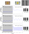
Response of one CurvACE element (a photodetector with optics) to sharp changes in the illuminance (obtained by opening a sun-blind) after digitizing and sampling the data at a frequency of 500 Hz. The photodetector output signal was recorded while facing a periodic pattern (a set of stripes with a width of 50 mm placed 195 mm from the sensor) exposed to natural lighting conditions) (a) stationary (static state) and translating at a speed of (b) 29°/s and (c) 172°/s. The photodetector compensated quickly (about 0.5 s) for the increase in the illuminance and adapted its gain, as well as amplified the transient signals generated by the moving pattern. The inset (upper right corner) shows the periodic pattern acquired by the CurvACE sensor at a distance of 15 cm with a region of interest composed of 20 by 15 ommatidia under a lighting of 1500 Lux.
Figure 15.
Figure 15.
(a) The CurvACE device placed in a circular arena (105 cm in diameter) lined with the CurvACE logo. The CurvACE supporting stage rotated around the vertical axis (red dotted line) at an angular speed of 125°/s by means of a stepper motor. (b) Images taken from three video sequences acquired by CurvACE under three different lighting conditions: 0.5 Lux, 700 Lux and 1500 Lux. The sensor is able to retain high sensitivity despite the strong differences in the ambient lighting.

References

    1. Land M.F., Nilsson D.E. Animal Eyes. Oxford University Press; Oxford, UK: 2012.
    1. Floreano D., Pericet-Camara R., Viollet S., Ruffier F., Brückner A., Leitel R., Buss W., Menouni M., Expert F., Juston R., et al. Miniature curved artificial compound eyes. Proc. Natl. Acad. Sci. 2013;110:9267–9272. - PMC - PubMed
    1. Brückner A., Duparré J., Bräuer A., Tünnermann A. Artificial compound eye applying hyperacuity. Opt. Express. 2006;14:12076–12084. - PubMed
    1. Duparré J., Wippermann F., Dannberg P., Bräuer A. Artificial compound eye zoom camera. Bioinspir. Biomim. 2008;3 doi: 10.1088/1748-3182/3/4/046008. - DOI - PubMed
    1. Jeong K.H., Kim J., Lee L.P. Biologically Inspired Artificial Compound Eyes. Science. 2006;312:557–561. - PubMed

Publication types

MeSH terms

LinkOut - more resources