

doi: 10.1177/108471389600100302.
Microcomputer applications for hearing aid selection and fitting
Affiliations
- PMID: 25425856
- PMCID: PMC4172261
- DOI: 10.1177/108471389600100302
Item in Clipboard
Microcomputer applications for hearing aid selection and fitting
Trends Amplif.
1996 Sep.
No abstract available
Figures

Subject data for an individual with moderate hearing loss given by the MSUv3.1 program.

Prescription for the hearing loss shown in Figure 1.

Thresholds, LDLs, REUR, and RECD values entered into the DSLv3.1 program.

Selection results calculated by DSLv3.1 for the patient in Figure 3.
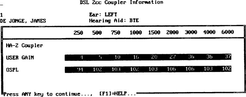
Target 2-cc coupler gain and OSPL90 recommended by DSLv3.1 for the patient in Figure 3.

Measured versus target gain (REIG) and output (RESR) computed by DSLv3.1.

Unaided results for the subject data described in Figures 3 to 6.

Aided results for the subject data described in Figures 3 to 6.

Threshold and audiometer calibration information is entered for the IHAFF procedure.

Contour data entered for 500 and 3000 Hz for the left ear.

Threshold and equal loudness contours for the data shown in Figure 10.
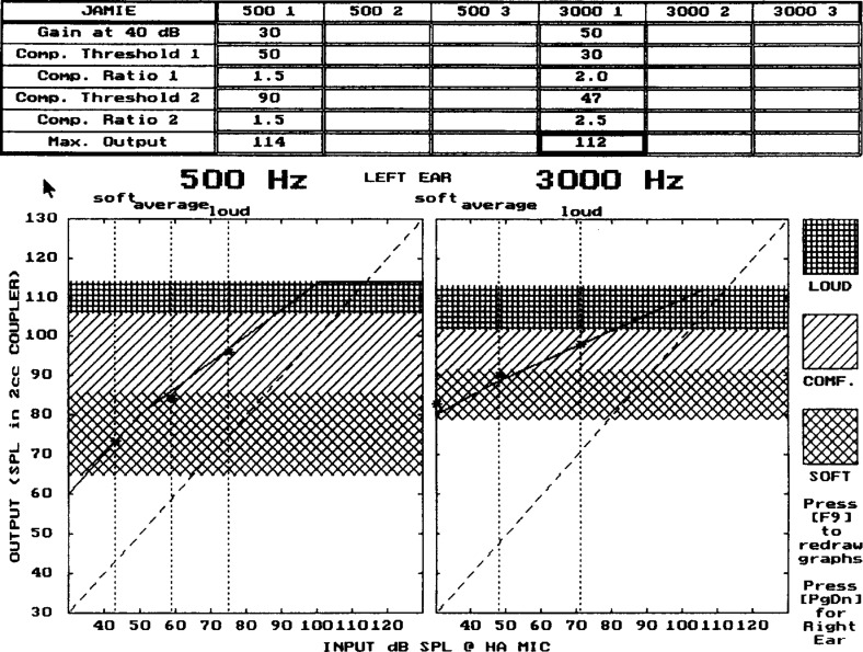
VIOLA graph showing possible choices for compression parameters defining the input-output function needed to hit the targets based on the loudness judgment shown in Figures 10 and 11.

Screen showing first question of the APHAB when the client enters data.

Display showing unaided results of the APHAB.

Display show aided results of the APHAB.

Display comparing the unaided and unaided results (benefit) of the APHAB.

Data entry screen for the Fig6 program.

Target coupler gain for 40, 65, and 95 dB inputs calculated by Fig6.

Audiogram data entry card for the SII calculations.

An example of aided SII calculations.
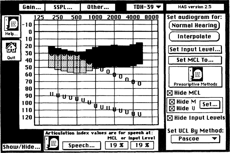
A sample screen from the HAS 2.5 program illustrating audiogram thresholds (O), loudness discomfort levels (U), and the audibility of the speech spectrum.
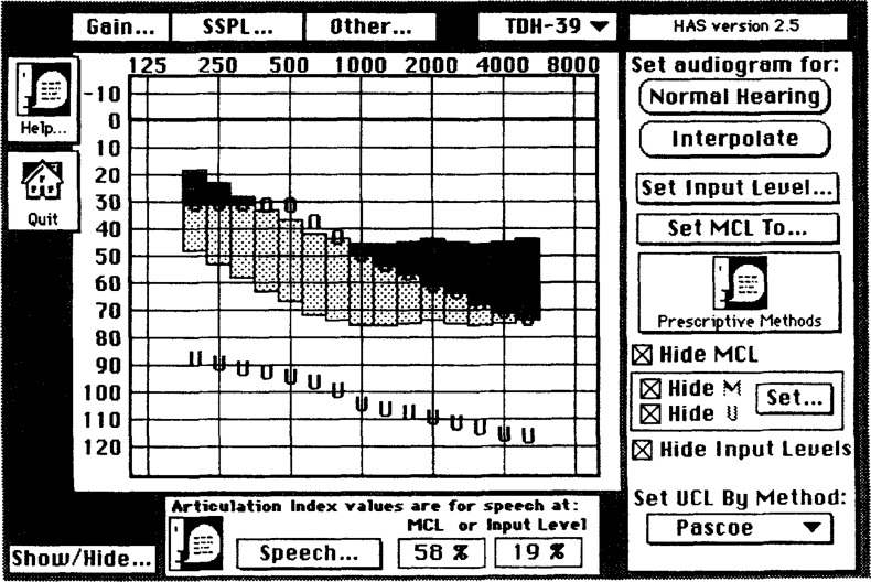
The same audiogram in Figure 21 after the speech spectrum has been amplified by the REIR specified by the NAL-R procedure.

Target REIR needed to produce the amplified speech spectrum shown in Figure 22. Three additonal level-dependent targets are displayed. These target were created by the LDN procedure.
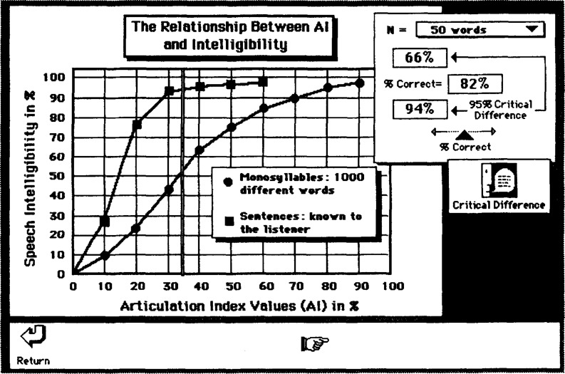
The relationship between articulation index values and speech intelligibility and critical differences.
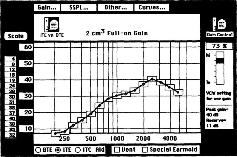
The HA-1 2-cc full-on gain needed to give the REIR shown in Figure 23.

Target HA-1 2-cc SSPL90 corresponding to the LDLs shown in Figures 21 and 22.
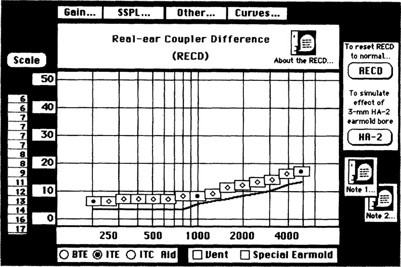
Card where custom values for the RECD can be entered.

Dynamic range compression ratios needed to map the normal dynamic range into the dynamic range shown in Figures 21 and 22.
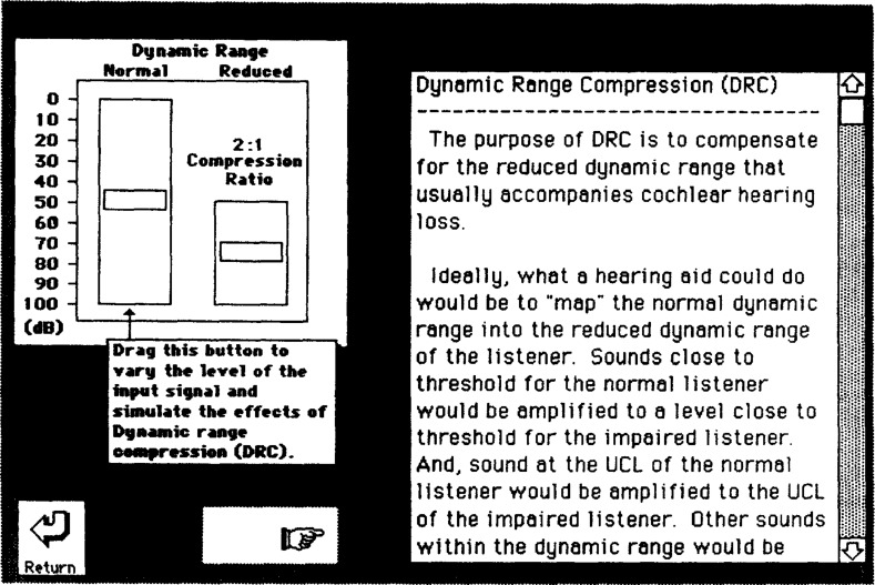
Tutorial information related to dynamic range compression.

Sample input-output functions for a set of compression parameters and the target needed to normalize loudness.

An example of calculations showing expected masking effect of noise.

Articulation index functions predicting the effect of noise upon speech intelligibility.

Options for parallel vents.

The “Specification” window from DSL 4.0 showing target OSPL90, gain, and compression ratios.

The “SPLogram - Verification” window. Target level-dependent frequency response curves are shown.

A sample DSL[i/o] input-output function along with the online help manual and tutorial.

A sample HASP screen showing the results of an automatic search for an ITE aid.

HASP display illustrating information available when used in the manual mode.
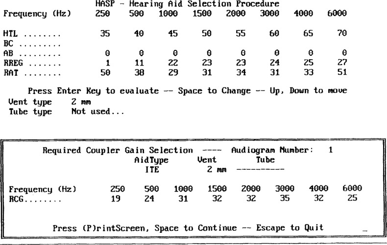
Coupler gain required to match the target REIR.

Similar articles
-
[Hearing aid selection and fitting from the pediatric audiology viewpoint].HNO. 1989 Oct;37(10):397-405. HNO. 1989. PMID: 2681090 Review. German.
-
Guidelines for the evaluation of hearing aid fitting (2010).Auris Nasus Larynx. 2016 Jun;43(3):217-28. doi: 10.1016/j.anl.2015.10.015. Epub 2015 Dec 2. Auris Nasus Larynx. 2016. PMID: 26654157 Review.
-
Exploring the Effects of the Narrative Embodied in the Hearing Aid Fitting Process on Treatment Outcomes.Ear Hear. 2015 Sep-Oct;36(5):517-26. doi: 10.1097/AUD.0000000000000157. Ear Hear. 2015. PMID: 25811932 Clinical Trial.
-
[The development of auditory performance and speech intelligibility at the early stage after hearing aid fitting in children with moderate or severe hearing loss].Lin Chuang Er Bi Yan Hou Tou Jing Wai Ke Za Zhi. 2013 Nov;27(22):1234-8. Lin Chuang Er Bi Yan Hou Tou Jing Wai Ke Za Zhi. 2013. PMID: 24616979 Chinese.
-
Personality, hearing problems, and amplification characteristics: contributions to self-report hearing aid outcomes.Ear Hear. 2007 Apr;28(2):141-62. doi: 10.1097/AUD.0b013e31803126a4. Ear Hear. 2007. PMID: 17496667
Cited by
-
Curriculum for graduate courses in amplification.Trends Amplif. 1998 Mar;3(1):6-44. doi: 10.1177/108471389800300102. Trends Amplif. 1998. PMID: 25425878 Free PMC article. No abstract available.
-
Using the Frye SPL Fitting Software to Fit Hearing Aids Incorporating Nonlinear Signal Processing.Trends Amplif. 1998 Dec;3(4):162-71. doi: 10.1177/108471389800300405. Trends Amplif. 1998. PMID: 25425884 Free PMC article. No abstract available.
References
-
- American National Standards Institute. (1969). American National Standard Methods for Calculation of the Articulation Index. (ANSI S3.5–1969). New York: ANSI
-
- American National Standards Institute. (Draft). American National Standard Methods for The Calculation of the Speech Intelligibility Index. (ANSI S3.79-Draft). New York: ANSI
-
- Bentler RA, Pavlovic CV. (1989). Transfer functions and correction factors used in hearing aid evaluation and research. Ear Hear 10: 58–63 - PubMed
-
- Bentler RA, Pavlovic CV. (1992). Addendum to “Transfer functions and correction factors used in hearing aid evaluation and research.” Ear Hear 13: 284–286 - PubMed
-
- Berger KW, Hagberg EN, Rane RL. (1979). Determining hearing aid gain. Hear Instr 30: 26–28,44.
LinkOut - more resources
Full Text Sources
Other Literature Sources