

Design and Fabrication of an Instrumented Handrim to Measure the Kinetic and Kinematic Information by the Hand of User for 3D Analysis of Manual Wheelchair Propulsion Dynamics
- PMID: 25426429
- PMCID: PMC4236804
Design and Fabrication of an Instrumented Handrim to Measure the Kinetic and Kinematic Information by the Hand of User for 3D Analysis of Manual Wheelchair Propulsion Dynamics
Abstract
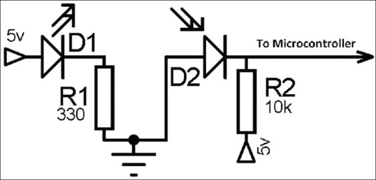
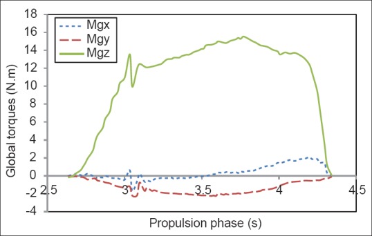
The repetitious nature of propelling a wheelchair has been associated with the high incidence of injury among manual wheelchair users (MWUs), mainly in the shoulder, elbow and wrist. Recent literature has found a link between handrim biomechanics and risk of injury to the upper extremity. The valid measurement of three-dimensional net joint forces and torques, however, can lead to a better understanding of the mechanisms of injury, the development of prevention techniques, and the reduction of serious injuries to the joints. In this project, an instrumented wheel system was developed to measure the applied loads dynamically by the hand of the user and the angular position of the wheelchair user's hand on the handrim during the propulsion phase. The system is composed of an experimental six-axis load cell, and a wireless eight channel data logger mounted on a wheel hub. The angular position of the wheel is measured by an absolute magnetic encoder. The angular position of the wheelchair user's hand on the handrim during the propulsion phase (ɸ) or point of force application (PFA) is calculated by means of a new-experimental method using 36 pairs of infrared emitter/receiver diodes mounted around the handrim. In this regard, the observed data extracted from an inexperienced able-bodied subject pushed a wheelchair with the instrumented handrim are presented to show the output behavior of the instrumented handrim. The recorded forces and torques were in agreement with previously reported magnitudes. However, this paper can provide readers with some technical insights into possible solutions for measuring the manual wheelchair propulsion biomechanical data.
Keywords: Biomechanics; handrim; instrumented wheel system; kinetic and kinematic; manual wheelchairs; propulsion analysis; six-axis load cell.
Conflict of interest statement
Figures


References
-
- Davis R, Ferrara M. The competitive wheelchair stroke. Natl Strength Cond Assoc. 1988;10:4–10.
-
- Gellman H, Chandler DR, Petrasek J, Sie I, Adkins R, Waters RL. Carpal tunnel syndrome in paraplegic patients. J Bone Joint Surg Am. 1988;70:517–9. - PubMed
-
- Apple DF, Cody R, Allen A. Overuse syndrome of the upper limb in people with spinal cord injury. Physical Fitness: A Guide for Individuals with Spinal Cord Injury. Journal of Rehabilitation Research and Development. 1996;(Chapter 5):97–108.
-
- Armstrong TJ, Fine LJ, Goldstein SA, Lifshitz YR, Silverstein BA. Ergonomics considerations in hand and wrist tendinitis. J Hand Surg Am. 1987;12:830–7. - PubMed
-
- Silverstein BA, Fine LJ, Armstrong TJ. Occupational factors and carpal tunnel syndrome. Am J Ind Med. 1987;11:343–58. - PubMed
LinkOut - more resources
Full Text Sources