. 2015 Mar;22(3):370-9.
doi: 10.1016/j.acra.2014.09.010. Epub 2014 Nov 27.

MR imaging near metallic implants using MAVRIC SL: initial clinical experience at 3T

Affiliations

MR imaging near metallic implants using MAVRIC SL: initial clinical experience at 3T

Luis B Gutierrez et al. Acad Radiol. 2015 Mar.

Abstract

Rationale and objectives: To compare the effectiveness of multiacquisition with variable resonance image combination selective (MAVRIC SL) with conventional two-dimensional fast spin-echo (2D-FSE) magnetic resonance (MR) techniques at 3T in imaging patients with a variety of metallic implants.

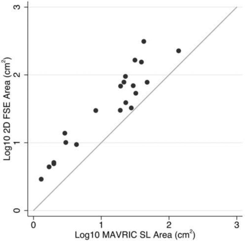
Materials and methods: Twenty-one 3T MR studies were obtained in 19 patients with different types of metal implants. Paired MAVRIC SL and 2D-FSE sequences were reviewed by two radiologists and compared for in-plane and through-plane metal artifact, visualization of the bone implant interface and surrounding soft tissues, blurring, and overall image quality using a two-tailed Wilcoxon signed rank test. The area of artifact on paired images was measured and compared using a paired Wilcoxon signed rank test. Changes in patient management resulting from MAVRIC SL imaging were documented.

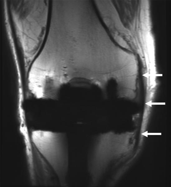
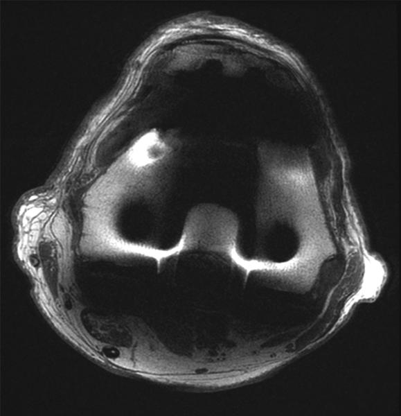
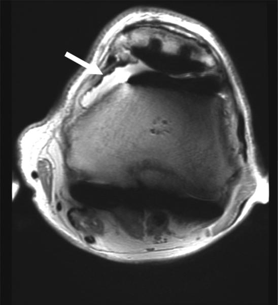
Results: Significantly less in-plane and through-plane artifact was seen with MAVRIC SL, with improved visualization of the bone-implant interface and surrounding soft tissues, and superior overall image quality (P = .0001). Increased blurring was seen with MAVRIC SL (P = .0016). MAVRIC SL significantly decreased the image artifact compared to 2D-FSE (P = .0001). Inclusion of MAVRIC SL to the imaging protocol determined the need for surgery or type of surgery in five patients and ruled out the need for surgery in 13 patients. In three patients, the area of interest was well seen on both MAVRIC SL and 2D-FSE images, so the addition of MAVRIC had no effect on patient management.

Conclusions: Imaging around metal implants with MAVRIC SL at 3T significantly improved image quality and decreased image artifact compared to conventional 2D-FSE imaging techniques and directly impacted patient management.

Keywords: MAVRIC SL; image quality; magnetic resonance imaging; metallic susceptibility artifact.


Figures

Figure 1
Figure 1
Pulse sequence diagram for MAVRIC SL, where RF is radiofrequency, Gz is the slice-select gradient, Gy is the phase-encoding gradient and Gx is the frequency-encoding gradient. The MAVRIC-SL sequence is based on a standard spin-echo-train imaging sequence (such as 3D FSE, Cube, Space, VISTA). The excitation and refocusing RF pulses are Gaussian shaped, with overlap between adjacent excited regions, which are typically about 8 - 12mm thick. Typically a reduced refocusing flip angle (135 or 120 degrees) is used instead of 180 degrees, to reduce SAR (specific absorption rate). Phase encoding in both slice and phase directions is used, allowing the sequence to resolve through-slice distortions. A view-angle-tilting (VAT) gradient is applied on the slice axis during the readout gradient to correct in-plane distortions.
Figure 2
Figure 2
(A) Axial inversion recovery and (B) axial MAVRIC SL inversion recovery images of the left hip in a 74-year-old woman with bilateral total hip arthroplasties and a painful left hip due to disruption of the gluteus minimus and medius tendons. An ovoid area of signal void is seen around the acetabular component, and the maximum area of artifact is measured in the same place on both images to allow quantitative comparison On the axial inversion recovery image the area of artifact measured 64.8 cm2, compared to 24.2 cm2 on the axial MAVRIC SL inversion recovery image. A small amount of fluid is seen lateral to the left hip, corresponding to fluid in the greater trochanteric bursa (arrow).
Figure 2
Figure 2
(A) Axial inversion recovery and (B) axial MAVRIC SL inversion recovery images of the left hip in a 74-year-old woman with bilateral total hip arthroplasties and a painful left hip due to disruption of the gluteus minimus and medius tendons. An ovoid area of signal void is seen around the acetabular component, and the maximum area of artifact is measured in the same place on both images to allow quantitative comparison On the axial inversion recovery image the area of artifact measured 64.8 cm2, compared to 24.2 cm2 on the axial MAVRIC SL inversion recovery image. A small amount of fluid is seen lateral to the left hip, corresponding to fluid in the greater trochanteric bursa (arrow).
Figure 3
Figure 3
(A) Coronal 2D FSE and (B) MAVRIC SL proton density-weighted images of the right knee following a total knee arthroplasty demonstrate significantly less metal artifact on MAVRIC SL images. This allows visualization of bone immediately adjacent to the prosthesis, and demonstrates an intact medial collateral ligament (arrows). (C) Axial 2D FSE and (D) MAVRIC SL proton density-weighted images in the same patient shows decreased in-plane artifact in the patella (P), trochlear (T) and posterior femur (F) on MAVRIC SL, and there is an absence of through-plane artifact (*) in the central femur on MAVRIC SL. A small joint effusion is clearly seen on MAVRIC SL (arrow).
Figure 3
Figure 3
(A) Coronal 2D FSE and (B) MAVRIC SL proton density-weighted images of the right knee following a total knee arthroplasty demonstrate significantly less metal artifact on MAVRIC SL images. This allows visualization of bone immediately adjacent to the prosthesis, and demonstrates an intact medial collateral ligament (arrows). (C) Axial 2D FSE and (D) MAVRIC SL proton density-weighted images in the same patient shows decreased in-plane artifact in the patella (P), trochlear (T) and posterior femur (F) on MAVRIC SL, and there is an absence of through-plane artifact (*) in the central femur on MAVRIC SL. A small joint effusion is clearly seen on MAVRIC SL (arrow).
Figure 4
Figure 4
Scatter plot comparing the area of artifact around implants on paired 2D FSE and MAVRIC SL images. A log scale was used for clarity. The diagonal line indicates identical X and Y values.
Figure 5
Figure 5
(A) Axial 2D FSE T2 and (B) Axial MAVRIC SL inversion recovery images of the sacrum in a 63-year-old male with acute onset of foot drop on the left after open reduction and internal fixation of complex pelvic and sacral fractures. The right L5 nerve root can be seen clearly in both images (arrowhead). The location of the left L5 nerve root is largely obscured by metal artifact on axial T2 (arrow) and visualization of the sacrum is limited. On the axial MAVRIC SL image the left L5 nerve root appears thickened (open arrow), and is in close proximity to the underlying sacral fracture (arrow).
Figure 5
Figure 5
(A) Axial 2D FSE T2 and (B) Axial MAVRIC SL inversion recovery images of the sacrum in a 63-year-old male with acute onset of foot drop on the left after open reduction and internal fixation of complex pelvic and sacral fractures. The right L5 nerve root can be seen clearly in both images (arrowhead). The location of the left L5 nerve root is largely obscured by metal artifact on axial T2 (arrow) and visualization of the sacrum is limited. On the axial MAVRIC SL image the left L5 nerve root appears thickened (open arrow), and is in close proximity to the underlying sacral fracture (arrow).
Figure 6
Figure 6
(A) AP radiograph of the pelvis in a 38 year-old male with a plated posterior acetabular wall fracture. (B) Coronal 2D FSE T1 and (C) coronal MAVRIC SL proton density-weighted images of the left hip. Significantly decreased artifact is seen on the MAVRIC SL, allowing visualization of a superior labral tear (arrow), and adjacent joint space narrowing.
Figure 6
Figure 6
(A) AP radiograph of the pelvis in a 38 year-old male with a plated posterior acetabular wall fracture. (B) Coronal 2D FSE T1 and (C) coronal MAVRIC SL proton density-weighted images of the left hip. Significantly decreased artifact is seen on the MAVRIC SL, allowing visualization of a superior labral tear (arrow), and adjacent joint space narrowing.
Figure 7
Figure 7
(A) Axial inversion recovery and (B) axial MAVRIC SL inversion recovery images of the left hip in a 64-year-old male with left hip pain after a resurfacing hip arthroplasty. Significantly decreased metal artifact is seen on MAVRIC SL images, although the images appear more blurry. A small focal fluid collection is seen on both sequences (arrowhead). However, the large joint effusion and synovitis (arrows) is only seen on MAVRIC SL. The effusion was aspirated, and subsequent steroid injection lead to symptomatic improvement.
Figure 7
Figure 7
(A) Axial inversion recovery and (B) axial MAVRIC SL inversion recovery images of the left hip in a 64-year-old male with left hip pain after a resurfacing hip arthroplasty. Significantly decreased metal artifact is seen on MAVRIC SL images, although the images appear more blurry. A small focal fluid collection is seen on both sequences (arrowhead). However, the large joint effusion and synovitis (arrows) is only seen on MAVRIC SL. The effusion was aspirated, and subsequent steroid injection lead to symptomatic improvement.

Similar articles

Cited by

References

    1. Schenck JF. The role of magnetic susceptibility in magnetic resonance imaging: MRI magnetic compatibility of the first and second kinds. Med Phys. 1996 Jun;23(6):815–850. - PubMed
    1. Hargreaves BA, Worters PW, Pauly KB, et al. Metal-induced artifacts in MRI. AJR Am J Roentgenol. 2011 Sep;197(3):547–555. - PMC - PubMed
    1. Harris CA, White LM. Metal artifact reduction in musculoskeletal magnetic resonance imaging. Orthop Clin North Am. 2006 Jul;37(3):349–359. - PubMed
    1. Lu W, Pauly KB, Gold GE, et al. SEMAC: Slice Encoding for Metal Artifact Correction in MRI. Magn Reson Med. 2009 Jul;62(1):66–76. - PMC - PubMed
    1. Hargreaves BA, Chen W, Lu W, et al. Accelerated slice encoding for metal artifact correction. J Magn Reson Imaging. 2010 Apr;31(4):987–996. - PMC - PubMed