. 2015 Feb:13:159-67.
doi: 10.1016/j.actbio.2014.11.030. Epub 2014 Nov 24.

High-strength, surface-porous polyether-ether-ketone for load-bearing orthopedic implants

Affiliations

High-strength, surface-porous polyether-ether-ketone for load-bearing orthopedic implants

Nathan T Evans et al. Acta Biomater. 2015 Feb.

Abstract

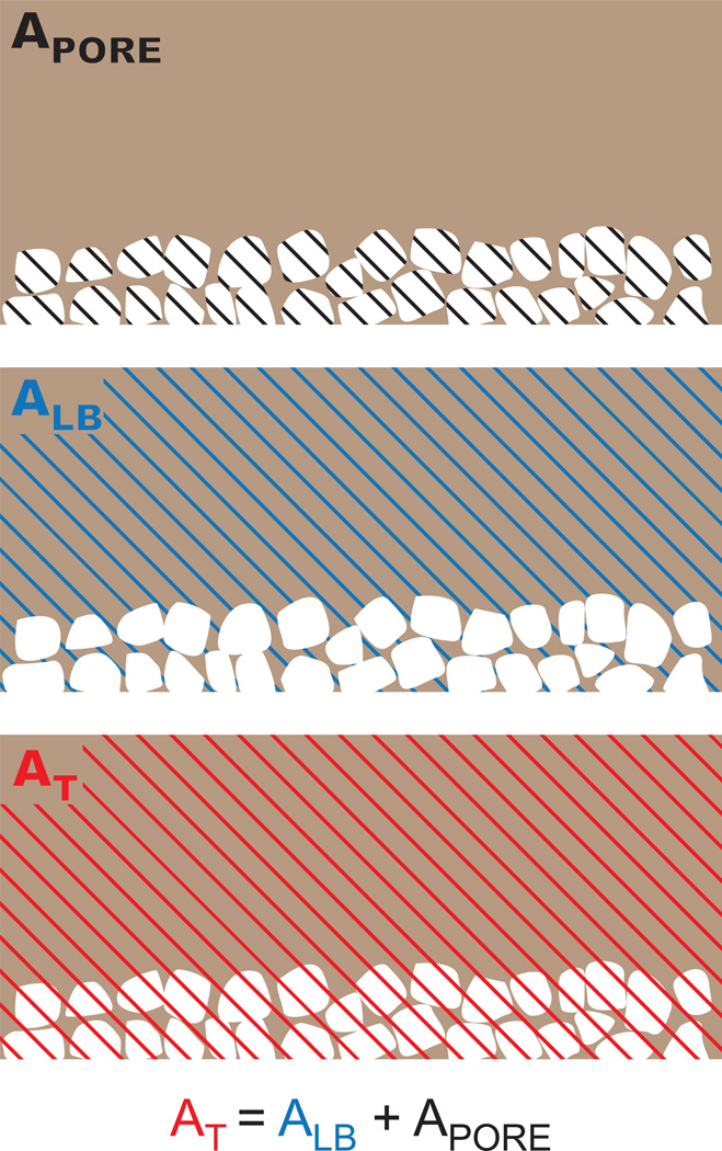
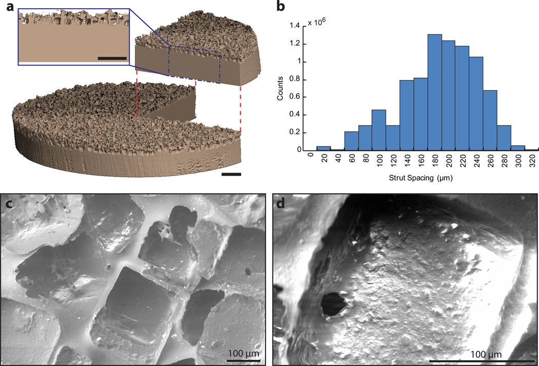
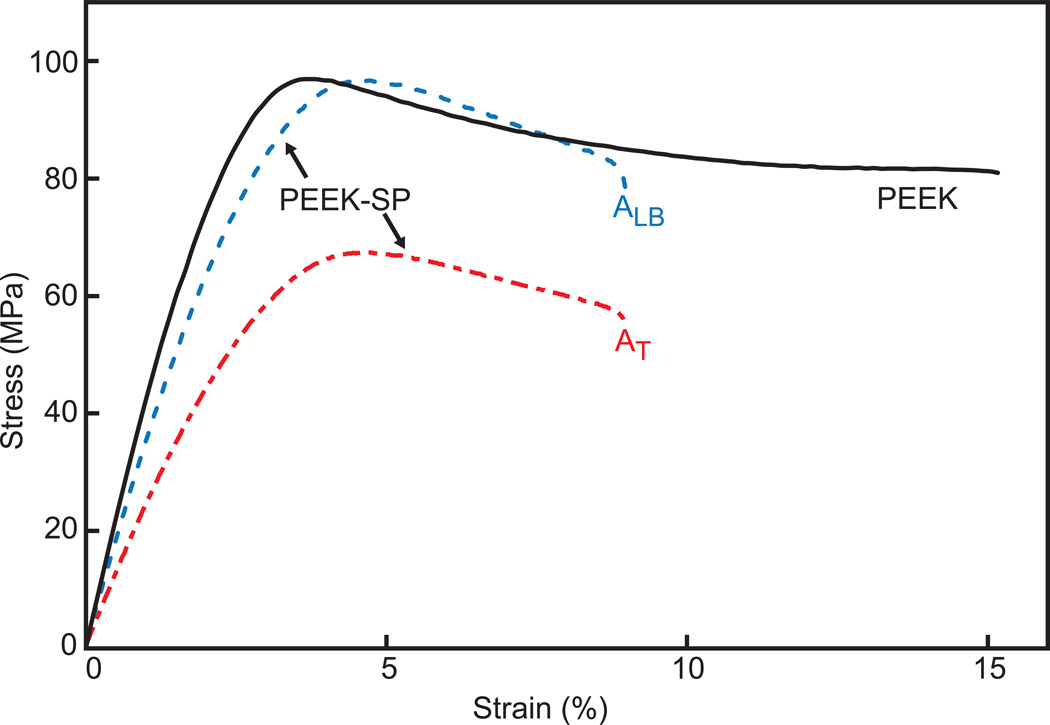
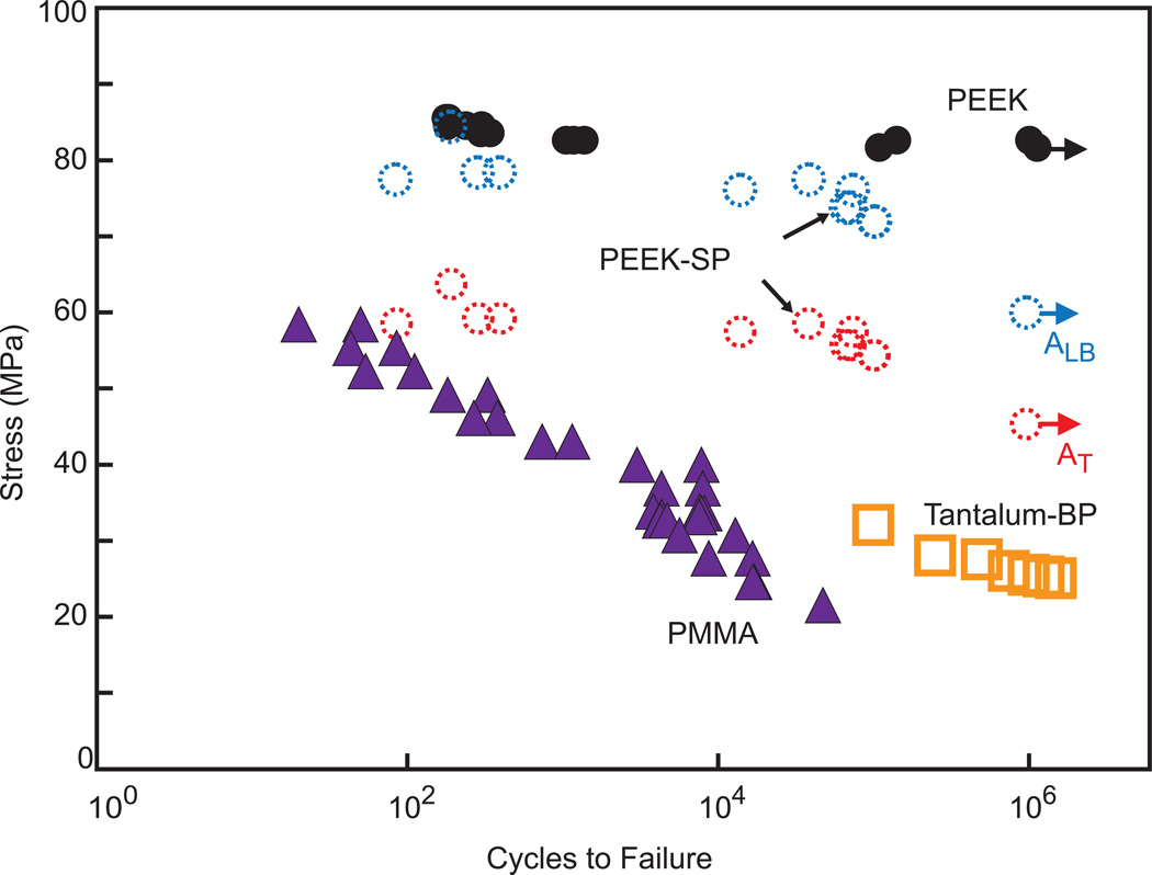
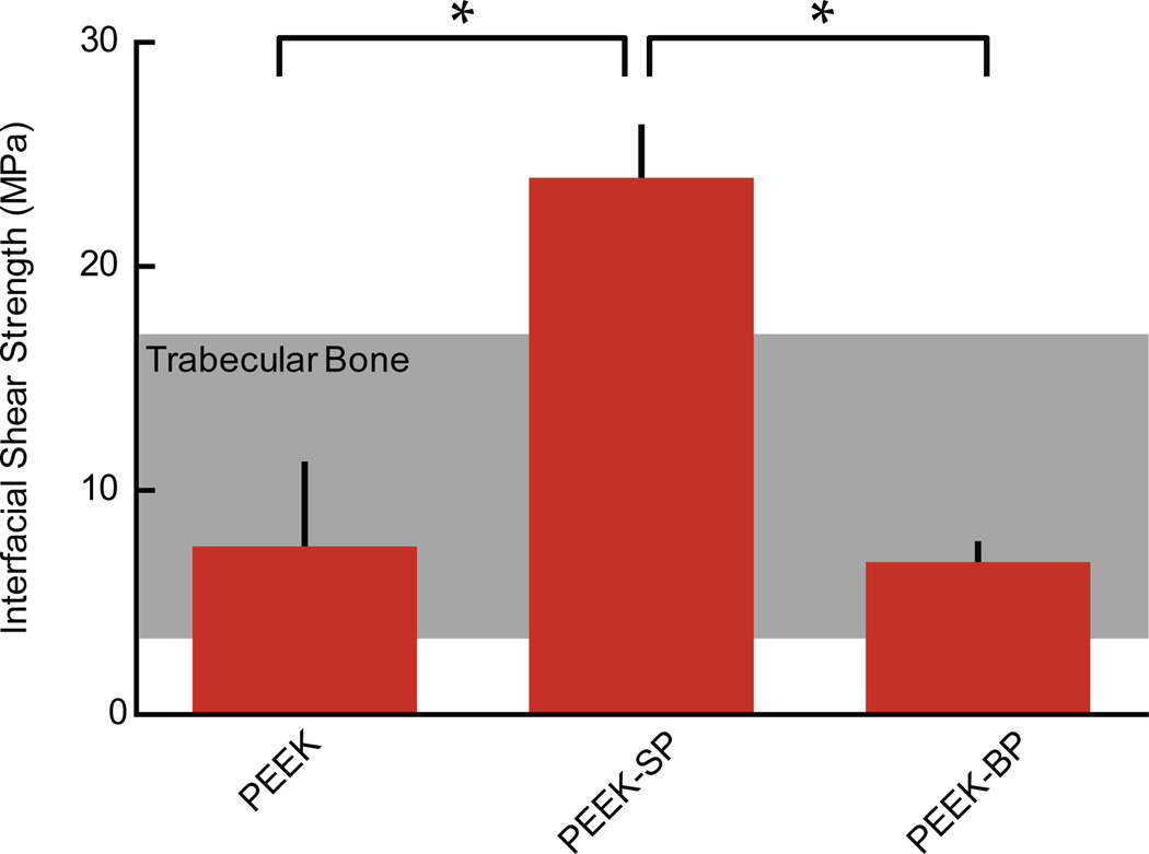
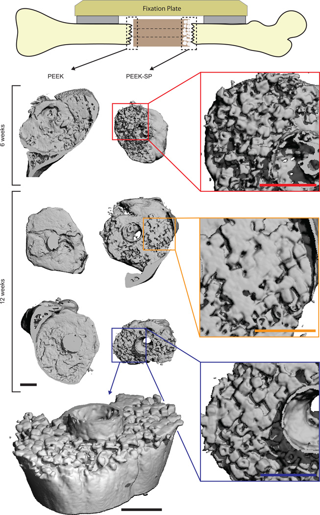
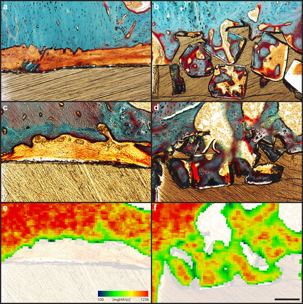
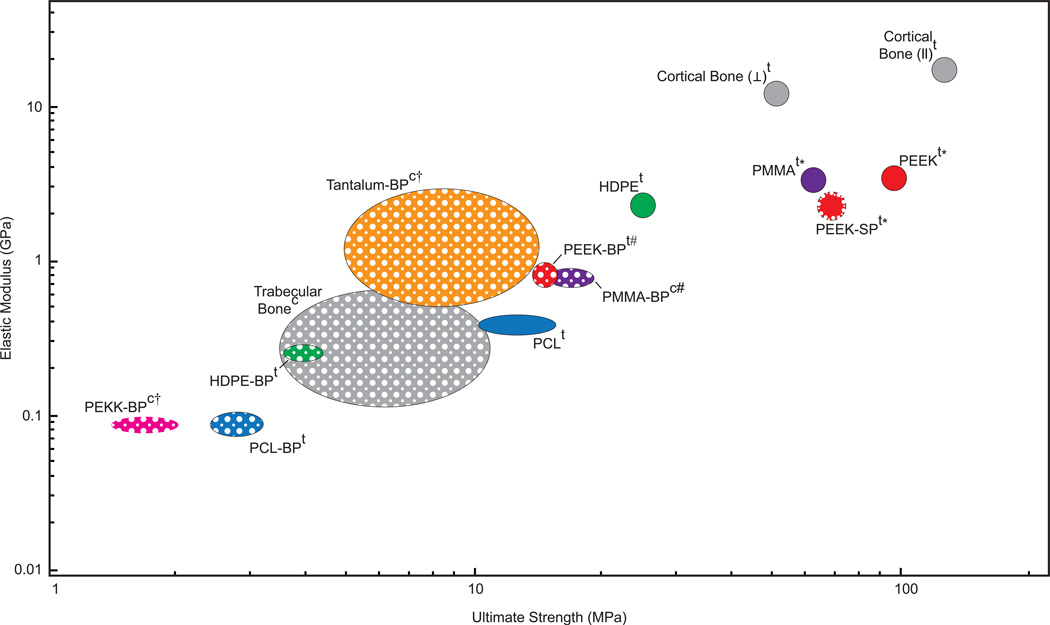
Despite its widespread clinical use in load-bearing orthopedic implants, polyether-ether-ketone (PEEK) is often associated with poor osseointegration. In this study, a surface-porous PEEK material (PEEK-SP) was created using a melt extrusion technique. The porous layer was 399.6±63.3 μm thick and possessed a mean pore size of 279.9±31.6 μm, strut spacing of 186.8±55.5 μm, porosity of 67.3±3.1% and interconnectivity of 99.9±0.1%. Monotonic tensile tests showed that PEEK-SP preserved 73.9% of the strength (71.06±2.17 MPa) and 73.4% of the elastic modulus (2.45±0.31 GPa) of as-received, injection-molded PEEK. PEEK-SP further demonstrated a fatigue strength of 60.0 MPa at one million cycles, preserving 73.4% of the fatigue resistance of injection-molded PEEK. Interfacial shear testing showed the pore layer shear strength to be 23.96±2.26 MPa. An osseointegration model in the rat revealed substantial bone formation within the pore layer at 6 and 12 weeks via microcomputed tomography and histological evaluation. Ingrown bone was more closely apposed to the pore wall and fibrous tissue growth was reduced in PEEK-SP when compared to non-porous PEEK controls. These results indicate that PEEK-SP could provide improved osseointegration while maintaining the structural integrity necessary for load-bearing orthopedic applications.

Keywords: Fatigue; Orthopedic implant; Polyether-ether-ketone (PEEK); Surface porous.


Figures

Fig. 1
Fig. 1
Schematic of the PEEK-SP cross-sectional areas used in stress calculations. The processing increases cross-sectional areas due to the creation of pores. However, the load-bearing area, ALB, is representative of the initial area of PEEK material, assuming volume conservation. The total area, AT, is the sum of the load-bearing area and the area of the pore network, APORE.
Fig. 2
Fig. 2
Microstructural characterization of PEEK-SP: (a) µCT reconstruction of PEEK-SP structure showing representative pore layer cross-section. Note the cubic pore morphology due to cubic sodium chloride crystals. Scale bar is 1 mm. (b) Strut spacing histogram as characterized by micro-CT. (c,d) SEM micrographs of the PEEK-SP pore network. Images confirm cubic pore morphology and pore interconnectivity detected by µCT.
Fig. 3
Fig. 3
Representative stress-strain curves of solid PEEK and PEEK-SP calculated using both ALB and AT.
Fig. 4
Fig. 4
S-N curve comparing the fatigue behavior of PEEK-SP using the load-bearing, ALB, and the total area, AT, to solid PEEK, PMMA, and bulk porous tantalum tested by another group [39]. Arrows denote tests that were halted after reaching 106 cycles (solid PEEK, PEEK-SP), which is defined as the runout stress.
Fig. 5
Fig. 5
Interfacial shear strength of PEEK-SP compared to smooth PEEK and sintered PEEK-BP with the shear strength of trabecular bone shown in the shaded region [48]. Asterisks (*) indicate p < 0.05.
Fig. 6
Fig. 6
µCT reconstructions of bone growth into PEEK-SP and adjacent to smooth PEEK surfaces (dashed boxes) at 6 and 12 weeks show the extent of bone ingrowth. Images are oriented with the lateral side on top. Insets show magnified views of ingrown bone. PEEK implants are not depicted due to thresholding difficulties of µCT reconstructions. An angled view is presented to visualize the extent of bone intrusion into the porous surface layer. Note the cubic morphology of bone in the surface porous PEEK samples, suggesting complete growth into the cubic pores. Scale bars on µCT images are 1 mm.
Fig. 7
Fig. 7
Bone ingrowth of PEEK-SP and smooth PEEK surfaces: (a,c) Representative histological images of fibrous tissue formation on smooth PEEK faces at six and twelve weeks, respectively. (b,d) Representative histological images of bone ingrowth within PEEK-SP faces at six and twelve weeks, respectively. Osteoid stained deep red; mineralized bone stained green; fibrous tissue stained light orange; and PEEK material is seen in brown. (e,f) Representative mineral attenuation maps from µCT at approximately the same cross sections as (c,d). Blue represents lower mineral density and red indicates high mineral density. Scale bar is 200 µm.
Fig. 8
Fig. 8
Ashby plot of elastic moduli and ultimate strengths for several orthopaedic biomaterials and bone that have been reported in the literature [, , –38]. Solid-filled ellipses represent fully dense materials and porous-filled ellipses represent porous materials. While cortical bone does possess low porosity, it is grouped with the fully dense materials for this comparison. Each material, with the exception of porous tantalum and polyether-ketone-ketone (PEKK), has both solid and porous properties included to illustrate the reduction in properties due to porosity. PEEK-SP is indicated by a porous layer outlining the solid-filled circle. Superscript ‘t’ refers to materials tested in tension and ‘c’ indicates compression. Daggers (†) indicate yield strengths where ultimate strength was not reported. Pound signs (#) indicate bending modulus when elastic modulus was not reported. Asterisks (*) indicate values tested by our group. Ellipse central location and size represents reported mean and plus or minus one standard deviation, respectively, where available.

References

    1. Place ES, Evans ND, Stevens MM. Complexity in biomaterials for tissue engineering. Nat Mater. 2009;8:457–470. - PubMed
    1. Nagels J, Stokdijk M, Rozing PM. Stress shielding and bone resorption in shoulder arthroplasty. Journal of Shoulder and Elbow Surgery. 2003;12:35–39. - PubMed
    1. Converse GL, Conrad TL, Roeder RK. Mechanical properties of hydroxyapatite whisker reinforced polyetherketoneketone composite scaffolds. Journal of the Mechanical Behavior of Biomedical Materials. 2009;2:627–635. - PubMed
    1. DiRienzo AL, Yakacki CM, Frensemeier M, Schneider AS, Safranski DL, Hoyt AJ, et al. Porous poly(para-phenylene) scaffolds for load-bearing orthopedic applications. Journal of the Mechanical Behavior of Biomedical Materials. 2014;30:347–357. - PubMed
    1. Pereira HD, Correlo V, Silva-Correia J, Oliveira J, Reis Ceng R, Espregueira-Mendes J. Migration of “bioabsorbable” screws in ACL repair. How much do we know? A systematic review. Knee Surgery, Sports Traumatology, Arthroscopy. 2013:1–9. - PubMed

Publication types