Review
. 2014 Dec 17:11:168.
doi: 10.1186/1743-0003-11-168.

Non-invasive control interfaces for intention detection in active movement-assistive devices

Affiliations
Review

Non-invasive control interfaces for intention detection in active movement-assistive devices

Joan Lobo-Prat et al. J Neuroeng Rehabil. .

Abstract

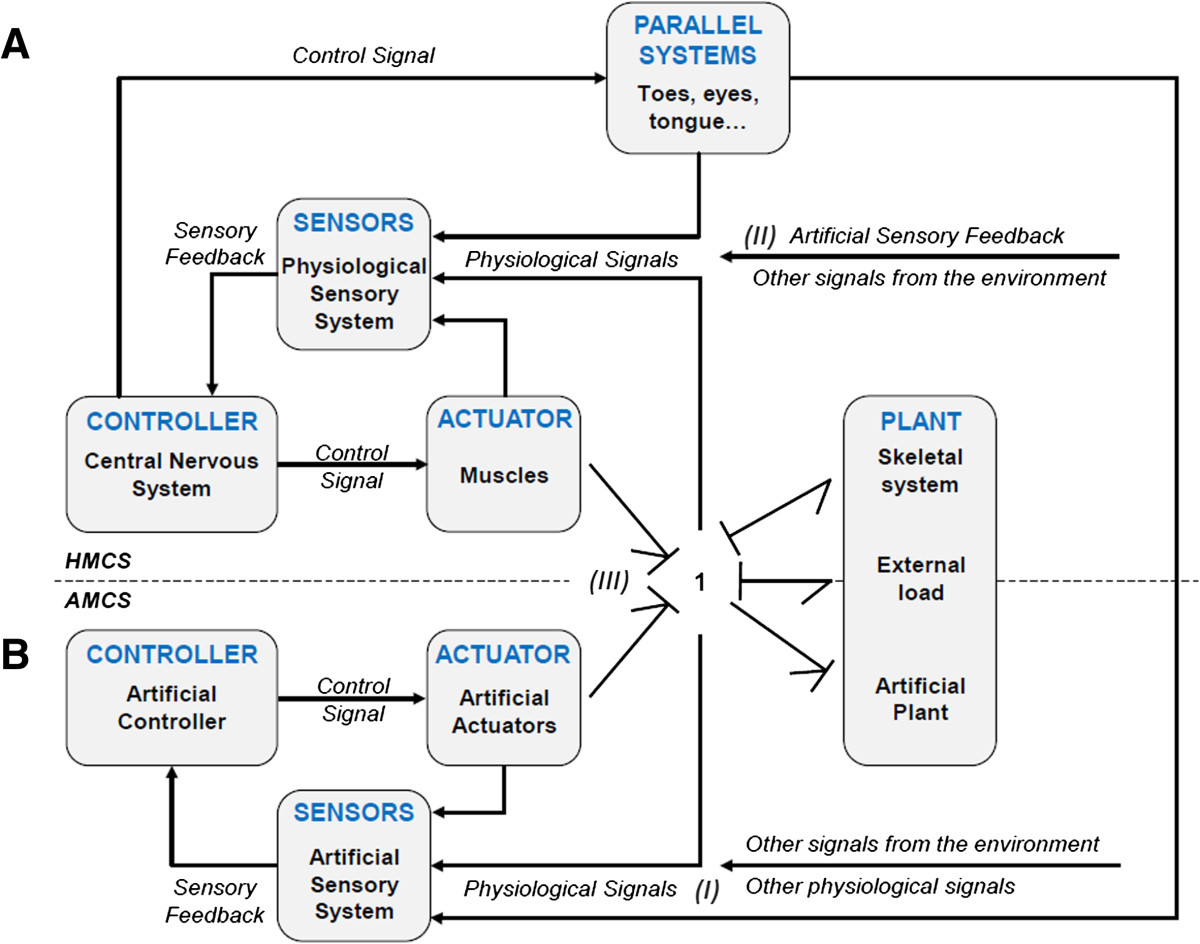
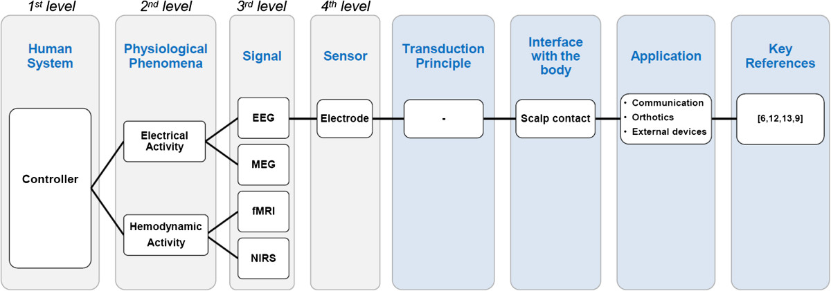
Active movement-assistive devices aim to increase the quality of life for patients with neuromusculoskeletal disorders. This technology requires interaction between the user and the device through a control interface that detects the user's movement intention. Researchers have explored a wide variety of invasive and non-invasive control interfaces. To summarize the wide spectrum of strategies, this paper presents a comprehensive review focused on non-invasive control interfaces used to operate active movement-assistive devices. A novel systematic classification method is proposed to categorize the control interfaces based on: (I) the source of the physiological signal, (II) the physiological phenomena responsible for generating the signal, and (III) the sensors used to measure the physiological signal. The proposed classification method can successfully categorize all the existing control interfaces providing a comprehensive overview of the state of the art. Each sensing modality is briefly described in the body of the paper following the same structure used in the classification method. Furthermore, we discuss several design considerations, challenges, and future directions of non-invasive control interfaces for active movement-assistive devices.


Figures

Figure 1
Figure 1
Schematic block diagram of the Human Movement Control System (A) in parallel with the Artificial Movement Control System (B). Three kinds of interactions between the HMCS and AMCS can be distinguished: (I) detection of the motion intention of the user; (II) provision of feedback to the user regarding the state of the AMCS, the HMCS or the environment; and (III) exchange of mechanical power between plants. Both the human and the artificial systems are depicted as dynamic systems in which both the human muscles and artificial actuators generate forces to transfer power and hence move the combined plant composed of the mechanical structure of the assistive device, the human musculoskeletal system and the environment (depicted as “external load”). Note that the interaction between the actuators and the plant is pictured with a bond graph that represents the energy exchange between them (i.e., movement and force in this particular case). The power 1-junction states a common velocity of all components. The reader is referred to [3] for further information on bond graphs. Modified from [1].
Figure 2
Figure 2
Classification Method. Example of the classification method illustrated with a schematic block diagram. See Table 1 for a full overview.
Figure 3
Figure 3
EEG-based interface. An EEG-based BCI used for the control of the Mindwalker lower-extremity exoskeleton [12, 87]. In this setup the BCI is controlled using Steady State Visually Evoked Potentials (SSVEP). The glasses that the user is wearing stimulate the retina with several flashing lights at different frequencies, and depending on which flashing light the users looks at, the brain will generate electrical activity at the same (or a multiple) frequency as the visual stimulus. With this method, different control states are assigned to the electrical brain signals with specific frequencies. Additional file 1 shows this EEG-based BCI controlling the Mindwalker lower-extremity exoskeleton. Figure courtesy of Mindwalker project.
Figure 4
Figure 4
EMG-based interface. An amputated patient using a Targeted Muscle Reinnervation (TMR) EMG-based interface for the control of an active prosthetic arm [116]. With the TMR EMG-based interface, the patient could control a 6 DOF prosthesis consisting of shoulder flexion, humeral rotation, elbow flexion, wrist rotation, wrist flexion, and hand opening/closing control. The movement performance of this 6 DOF prosthesis (right arm) controlled with TMR EMG-based interface was evaluated and compared to the commercially available prosthesis (left arm) with 3 DOF (body-powered elbow and wrist rotation, and active terminal device) during several timed tasks: A) cubbies, B) cups, C) Box and blocks, and D) clothespin relocation task. The participant could control up to 4 DOF simultaneously, reach a larger workspace and perform some of the timed tasks faster using the TMR EMG-based interface. Figure reused with permission from Elsevier.
Figure 5
Figure 5
Muscle-force-based interface. The prosthesis is controlled by pulling on cables that mechanically link the tendons attached to the tunnel muscle cineplasty to a force transducer mounted to the thumb of the prosthetic hand. An artificial controller measures the tendon force produced by the muscle to operate the opening and closing of the hand. A) schematic representation of the prosthesis and the control interface, B) an early version of the prototype without a cosmetic hand glove, C) the final prototype of the prosthesis with a cosmetic hand glove. Figure modified from [46].
Figure 6
Figure 6
Joint-rotation-based interface. 2 DOF joystick used for the control of a prosthetic arm (shoulder flexion-extension, shoulder internal-external rotation) with the residual shoulder motion. A) Diagram of the control interface used to measure the residual shoulder motion, B) close-up of the prototype, C) shoulder elevation produces shoulder flexion, D) shoulder depression produces shoulder extension, E) shoulder protraction produces internal shoulder rotation, F) shoulder retraction produces external shoulder rotation. Additional file 3 shows an amputee using this shoulder-joystick-based interface to control the shoulder motions of an active prosthesis. Figure modified from [56].
Figure 7
Figure 7
Force-based interface. An adult man with Duchenne muscular dystrophy with no arm function left using a force-based interface to operate an active elbow orthosis [62]. The force sensor measures the interaction force between the orthosis and the user, which is used as a control input for an admittance controller. A critical aspect for the usability of this interface is the accurate identification of the gravitational and joint stiffness forces (which are pose-dependent) required to distinguish the low-amplitude voluntary forces of the user. Additional file 4 shows the force calibration procedure used to identify the gravitational and joint stiffness forces. Additional file 5 shows a man with Duchenne muscular dystrophy performing a discrete tracking task using the force-based interface to control the active elbow orthosis. Figure courtesy of Flextension project.
Figure 8
Figure 8
Tongue-movement-based interfaces. The tongue-movement-based interface developed by [76]. This system has two inductive coils mounted at the lateral parts of the mouth and a ferromagnetic material attached at the tip of the tongue. The users generate control commands by moving the tongue to one of the user-defined locations. Tongue movement interfaces take advantage of the fact that highly paralyzed patients generally have tongue control and they can move it very rapidly and accurately within the oral space. Additional file 6 shows a SCI patient performing a driving task with a wheelchair that is controlled with this tongue-movement-based interface. Figure courtesy of Dr. Maysam Ghovanloo.

References

    1. Veltink PH. Sensory feedback in artificial control of human mobility. Technol Health Care. 1999;7:383–391. - PubMed
    1. Veltink PH, Koopman HFJM, van der Helm FCT, Nene AV. Biomechatronics – assisting the impaired motor system. Arch Physiol Biochem. 2001;109:1–9. doi: 10.1076/apab.109.1.1.4282. - DOI - PubMed
    1. Borutzky W. Bond Graph Methodology: Development and Analysis of Multidisciplinary Dynamic System Models. Switzerland: Springer International publisher; 2010.
    1. Dollar AM, Herr H. Lower extremity exoskeletons and active orthoses: challenges and state-of-the-Art. IEEE Trans Robot. 2008;24:144–158. doi: 10.1109/TRO.2008.915453. - DOI
    1. Pons JL. Wearable Robots: Biomechatronic Exoskeletons. 1 2008.

Publication types