. 2015 Feb:41:151-65.
doi: 10.1016/j.biomaterials.2014.11.035. Epub 2014 Dec 9.

Microchannel-based regenerative scaffold for chronic peripheral nerve interfacing in amputees

Affiliations

Microchannel-based regenerative scaffold for chronic peripheral nerve interfacing in amputees

Akhil Srinivasan et al. Biomaterials. 2015 Feb.

Abstract

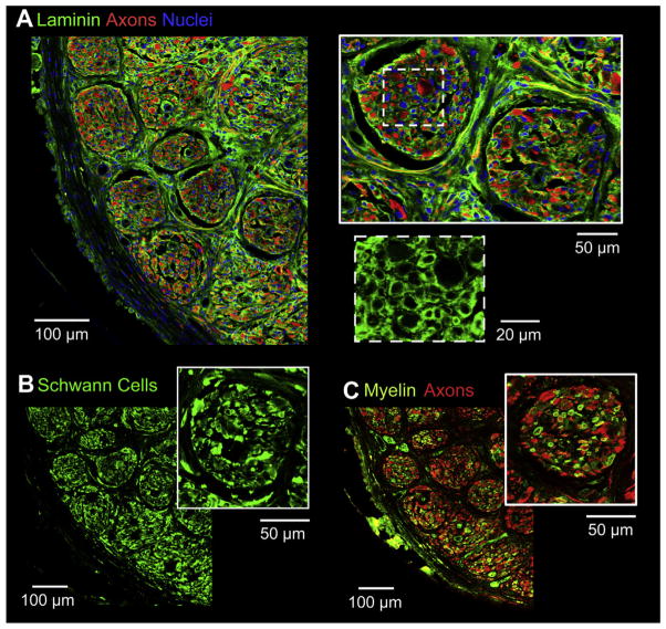
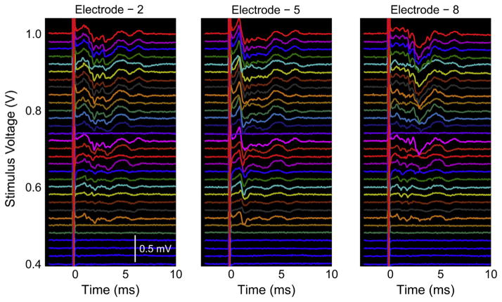
Neurally controlled prosthetics that cosmetically and functionally mimic amputated limbs remain a clinical need because state of the art neural prosthetics only provide a fraction of a natural limb's functionality. Here, we report on the fabrication and capability of polydimethylsiloxane (PDMS) and epoxy-based SU-8 photoresist microchannel scaffolds to serve as viable constructs for peripheral nerve interfacing through in vitro and in vivo studies in a sciatic nerve amputee model where the nerve lacks distal reinnervation targets. These studies showed microchannels with 100 μm × 100 μm cross-sectional areas support and direct the regeneration/migration of axons, Schwann cells, and fibroblasts through the microchannels with space available for future maturation of the axons. Investigation of the nerve in the distal segment, past the scaffold, showed a high degree of organization, adoption of the microchannel architecture forming 'microchannel fascicles', reformation of endoneurial tubes and axon myelination, and a lack of aberrant and unorganized growth that might be characteristic of neuroma formation. Separate chronic terminal in vivo electrophysiology studies utilizing the microchannel scaffolds with permanently integrated microwire electrodes were conducted to evaluate interfacing capabilities. In all devices a variety of spontaneous, sensory evoked and electrically evoked single and multi-unit action potentials were recorded after five months of implantation. Together, these findings suggest that microchannel scaffolds are well suited for chronic implantation and peripheral nerve interfacing to promote organized nerve regeneration that lends itself well to stable interfaces. Thus this study establishes the basis for the advanced fabrication of large-electrode count, wireless microchannel devices that are an important step towards highly functional, bi-directional peripheral nerve interfaces.

Keywords: Microchannel; Nerve guide; Nerve regeneration; Neural interfacing; Peripheral nerve interfacing; Polydimethylsiloxane.


Figures

Fig. 1
Fig. 1
(A) Overview of the rat amputee model depicting the site of implantation, tracing of subcutaneous wires, and percutaneous headstage for neural interfacing. (B) Schematic of microchannel architecture detailing materials, dimensions, and possible layout of incorporated gold electrodes. (C) Depiction of final microchannel scaffold after rolling for implantation. Adapted from Ref. [23].
Fig. 2
Fig. 2
Overview of all major fabrication processes for the regenerative microchannel scaffolds along with schematics depicting the device in each step. ‘Open’ microchannels from step 5 were used in in vitro studies. In vivo studies used microchannels from step 10. Drawings are not to scale.
Fig. 3
Fig. 3
(A) Image of ‘open’ microchannels corresponding to step 5 in Fig. 2. (B) Image of microchannels with the PDMS cover layer adhered to the SU-8 walls corresponding to step 10 in Fig. 2. (C) Cross-sectional view of 100 μm × 100 μm microchannel scaffold rolled for implantation. (D) Close up of rolled microchannel scaffold showing neighboring microchannel layers delineated by a red line. (For interpretation of the references to color in this figure legend, the reader is referred to the web version of this article.)
Fig. 4
Fig. 4
(Main image) DRG in vitro culture with axon processes and migrating Schwann cells on ‘open’ 50 μm wide microchannels. (A) and (B) Axons and Schwann cells were aligned and oriented in the microchannels and grew/migrated out to 4 mm in some cases. (C) Growth and migration of axons and Schwann cells re-orienting towards the microchannels. Axons (red); Schwann cells (green); DRG and regions of axon/Schwann cell co-localization appear orange/yellow; Microchannels are visible as dark horizontal regions separated by auto-fluorescent SU-8 microchannel walls; Arrowheads indicate axons; Arrows indicate Schwann cells; Scale bar = 200 μm unless otherwise noted. (For interpretation of the references to color in this figure legend, the reader is referred to the web version of this article.)
Fig. 5
Fig. 5
(A) Representative cross-sectional comparison of axon (red) profiles through the scaffolding among the three different microchannel dimensions: 50 μm × 100 μm; 100 μm × 100 μm; 150 μm × 100 μm, respectively. Cross-sections were taken at the midpoint of each scaffold. Arrows indicate microchannels containing axons. Arrowheads indicate microchannels lacking axons. (B) Quantitative analysis on the percent of microchannels in a scaffold containing regenerated axons for each microchannel dimension. (C) Close up of 100 μm × 100 μm scaffold cross-section depicting single axons profiles within microchannels. (D) Quantitative analysis on the percent of microchannels within the 100 μm × 100 μm microchannel scaffolds containing axon populations of 0–10, 11–100, or 100+ axons. (Mean ± S.E.M., ***p < 0.001). (For interpretation of the references to color in this figure legend, the reader is referred to the web version of this article.)
Fig. 6
Fig. 6
(A) Representative cross section of 100 μm × 100 μm microchannel scaffold stained for fibroblasts (red). Cross-sections were taken near the midpoint of the scaffold. (B) Close up of microchannels with delineations of microchannel area (yellow) and positive fibroblast staining used as a proxy for tissue cross-sectional area (green). (C) Quantitative analysis on the percent of microchannels within the 100 μm × 100 μm microchannel scaffolds with 0–25%, 25–50%, 50–75%, and 75–100% area filled with tissue. (Mean ± S.E.M.,*p < 0.05, **p < 0.01, ***p < 0.001). (For interpretation of the references to color in this figure legend, the reader is referred to the web version of this article.)
Fig. 7
Fig. 7
(A) Distal nerve cross-sections stained for axons (red) at increasing distances away from the scaffold (left image is the scaffold mid-section for reference). (B–D) Nerve cross-sections distal to the scaffolding. (B) Close up of distal nerve cross-section stained for axons (red) showing aggregates of axons. (C) Distal nerve cross-section stained for fibroblasts (red) and Schwann cells (green/yellow) showing perineurial like structures. (D) Distal nerve cross-section stained for laminin (green) and axons (red) showing basal lamina and connective tissue. (For interpretation of the references to color in this figure legend, the reader is referred to the web version of this article.)
Fig. 8
Fig. 8
(A) Close up of distal nerve cross section stained for laminin (green), axons (red), and cell nuclei (blue). Microchannel fascicles shown in the top right insert. Bottom right insert depicts a close up of the basal laminae structure. (B) Aggregates of Schwann cells (green) and (C) re-myelinated axons, shown by co-localization of myelin (green) and axons (red), were spatially correlated within microchannel fascicles. (For interpretation of the references to color in this figure legend, the reader is referred to the web version of this article.)
Fig. 9
Fig. 9
Images of a representative microchannel interface with microwire electrodes. (A) Proximal view. (B) Distal view with microwire electrodes entering the microchannels. (C) Side view.
Fig. 10
Fig. 10
Representative sensory evoked single unit action potential recording through an electrode in a microchannel interface. (A) Action potential waveform. (B) Raw recording signal over 4 s of plantar flexion followed by 4 s lacking plantar flexion. Plantar flexion was released at time = 61 s and is denoted by a motion artifact during release of the ankle. (C) Spike rate of the action potential where plantar flexion was held for 60 s, released for 30 s, and repeated. A 1 s bin size was used to generate the plot.
Fig. 11
Fig. 11
Representative electrically evoked multi-unit activity with different amplitudes, latencies, and waveforms from 3 representative electrodes in a microchannel interface.

References

    1. Navarro X, Krueger TB, Lago N, Micera S, Stieglitz T, Dario P. A critical review of interfaces with the peripheral nervous system for the control of neuro-prostheses and hybrid bionic systems. J Peripher Nerv Syst. 2005;10:229–58. - PubMed
    1. Fitzgerald JJ, Lacour SP, McMahon SB, Fawcett JW. Microchannels as axonal amplifiers. IEEE Trans Biomed Eng. 2008;55:1136–46. - PubMed
    1. Grill WM, Mortimer JT. Neural and connective tissue response to long-term implantation of multiple contact nerve cuff electrodes. J Biomed Mater Res. 2000;50:215–26. - PubMed
    1. Tyler DJ, Durand DM. Functionally selective peripheral nerve stimulation with a flat interface nerve electrode. IEEE Trans Neural Syst Rehabil Eng. 2002;10:294–303. - PubMed
    1. Branner A, Stein RB, Fernandez E, Aoyagi Y, Normann RA. Long-term stimulation and recording with a penetrating microelectrode array in cat sciatic nerve. IEEE Trans Biomed Eng. 2004;51:146–57. - PubMed

Publication types