. 2015 Jan 6;112(1):136-41.
doi: 10.1073/pnas.1411761112. Epub 2014 Dec 22.

Helical buckling of actin inside filopodia generates traction

Affiliations

Helical buckling of actin inside filopodia generates traction

Natascha Leijnse et al. Proc Natl Acad Sci U S A. .

Abstract

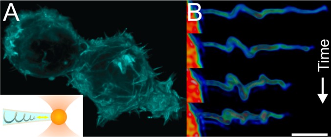
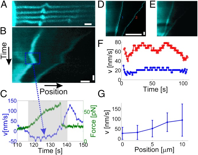
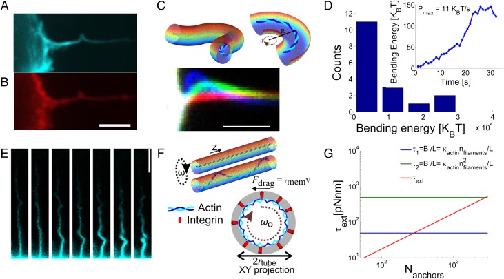
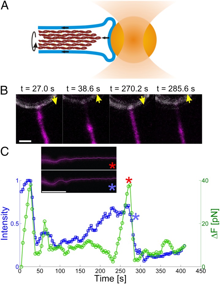
Cells can interact with their surroundings via filopodia, which are membrane protrusions that extend beyond the cell body. Filopodia are essential during dynamic cellular processes like motility, invasion, and cell-cell communication. Filopodia contain cross-linked actin filaments, attached to the surrounding cell membrane via protein linkers such as integrins. These actin filaments are thought to play a pivotal role in force transduction, bending, and rotation. We investigated whether, and how, actin within filopodia is responsible for filopodia dynamics by conducting simultaneous force spectroscopy and confocal imaging of F-actin in membrane protrusions. The actin shaft was observed to periodically undergo helical coiling and rotational motion, which occurred simultaneously with retrograde movement of actin inside the filopodium. The cells were found to retract beads attached to the filopodial tip, and retraction was found to correlate with rotation and coiling of the actin shaft. These results suggest a previously unidentified mechanism by which a cell can use rotation of the filopodial actin shaft to induce coiling and hence axial shortening of the filopodial actin bundle.

Keywords: filopodia rotation; filopodial retrograde flow; helical buckling; membrane nanotubes; membrane–cytoskeleton interactions.


Conflict of interest statement

The authors declare no conflict of interest.

Figures

Fig. 1.
Fig. 1.
Actin dynamics inside filopodia studied by simultaneous force spectroscopy and confocal microscopy. (A) HEK293 cells display a high density of short filopodia on their surface as visualized by fluorescently labeled F-actin (GFP-Utrophin). Inset shows schematics of the F-actin inside a filopodium held in place by an optically trapped bead (diameter = 4.95 μm) showing helical bending of the actin shaft. The yellow double arrow indicates the observed dynamic movement of the actin near the tip of the filopodium. (B) Deconvoluted 3D reconstruction of the fluorescently labeled F-actin (GFP-Utrophin) inside an extended filopodium. The images are taken at times t = 50.4, 84.0, 100.8, and 151.2 s after extension with an optically trapped bead. (Scale bar: 3 μm.)
Fig. 2.
Fig. 2.
Quantification of the velocity of actin coils traveling toward the cell body. (A) Progressive bending and traveling of two coils. The four images show the same actin filament at four consecutive time points (t1 = 75.9 s, t2 = 91.5 s, t3 = 93.6 s, and t4 = 116.5 s). Notably, the leftmost coil initially points upward and gradually rotates ∼180°. (Scale bar: 1 μm.) See also Movie S2. (B) Kymograph of the coils in A showing the positions of the coils versus time. Importantly, the position of the coil is consistently quantified in the reference frame of the trapped bead. The blue dashed rectangle shows the occurrence of a reversal in the velocity of the coil relative to the trapped bead. (Scale bars: 1 μm and 10 s.) (C) Quantification of the coil velocity (blue) and the corresponding pulling force on the trapped bead (green). The gray shaded area denotes the approximate time interval during which the velocity becomes negative in B. (D and E) Examples of two coils located at different distances relative to the cell body and traveling at different velocities. The positions of the coils are shown in D; these were found as the maximum of the intensity gradient of the raw data shown in E. (Scale bars: 5 μm and 10 s.) (F) The velocities of the two coils in D; the blue curve is from the left coil, and the red is from the right coil. (G) Distribution of velocities from n = 40 coils as a function of distance from the cell body. Error bars denote ±1SD.
Fig. 3.
Fig. 3.
Helical bending dynamics of actin filaments inside filopodia. (A and B) Bending of the F-actin (A) also induces a local bending of the membrane (labeled with DiD) as shown in B. (Scale bar: 3 μm.) (C) Plot of a tube, containing F-actin, which is bent into an arc of radius R. The overlay images below show progressive buckling of an actin bundle near the cell body. The colors represent three different relative time points at tred = 0 s, tgreen = 13 s, and tblue = 30 s. (Scale bar: 2 μm.) (D) Histogram of the maximum bending energy calculated from n = 17 filopodia displaying different degrees of bending. The energy is calculated assuming a bundle of 10 parallel actin filaments. The Inset shows the progressive increase in curvature energy versus time for the single buckle shown in C. The highest power consumed to bend the actin bundle reaches 11 KBT/s. (E) Example of a coiled actin structure inside a filopodium captured at different time points separated by 2 s. (Scale bar: 3 μm.) See also Movie S3. (F) Axial rotation of the actin within the membrane tube leads to friction between the membrane and the actin. Two initial scenarios depicting an actin filament within a membrane tube. In a filopodium, the actin will align along the inner membrane either as a straight rod (upper sketch) or a deformed shape, possibly a helix (lower sketch), within the tube. We model the actin–membrane linkages as connections between the actin and transmembrane integrins as shown by the XY projection of the membrane tube with an actin filament tracing a helix (with same radius as the tube) within the tube. The integrins (red cylinders) are dragged through the membrane by the rotating actin filament. (G) The total external torque on the actin shaft depends linearly on the number of anchors, Nanchors, connecting the actin with the membrane. Two critical buckling torques, τcrit, are plotted by the horizontal lines; these correspond to an actin shaft consisting of 10 actin filaments that are cross-linked (green line) or not cross-linked (blue line).
Fig. 4.
Fig. 4.
Force generation correlates with presence of actin at the tip of the filopodium. (A) Schematics of the attachment of the filopodium to the trapped bead. A small patch of membrane adheres to the bead substrate, thus allowing actin to bind to a fixed membrane at the tip. Binding of actin to the side walls of the tubular and fluid membrane results in a frictional dissipative force during rotation and directed flow of actin. (B) Images of the F-actin (magenta, labeled with Lifeact-GFP) at the tip of the filopodium overlaid with the reflection signal from the trapped bead (white). Correlation of successive detachment and reattachment of the actin to the bead with the forces exerted reveal a load-and-fail behavior of the actin filaments at the tip. Yellow arrows show the direction of movement of the optically trapped bead. See also Movie S4. (C) Quantification of the results shown in B. The blue curve shows the intensity of actin at the tip of the filopodium (see Movie S5 and SI Appendix, Fig. S11, for details). The green curve shows the change in the pulling force on the bead in the optical trap. The red and blue asterisks mark two time points; red, just before detachment of actin from the tip; blue, just after detachment of actin from the tip. The corresponding images (Inset) reveal that bending of the actin (shown by the solid line, which is the tracked skeleton of the actin shaft) is present both before and after release of tension.

References

    1. Murphy DA, Courtneidge SA. The “ins” and “outs” of podosomes and invadopodia: Characteristics, formation and function. Nat Rev Mol Cell Biol. 2011;12(7):413–426. - PMC - PubMed
    1. Mattila PK, Lappalainen P. Filopodia: Molecular architecture and cellular functions. Nat Rev Mol Cell Biol. 2008;9(6):446–454. - PubMed
    1. Möller J, Lühmann T, Chabria M, Hall H, Vogel V. Macrophages lift off surface-bound bacteria using a filopodium-lamellipodium hook-and-shovel mechanism. Sci Rep. 2013;3:2884. - PMC - PubMed
    1. Chan CE, Odde DJ. Traction dynamics of filopodia on compliant substrates. Science. 2008;322(5908):1687–1691. - PubMed
    1. Wang Y, et al. Visualizing the mechanical activation of Src. Nature. 2005;434(7036):1040–1045. - PubMed

Publication types

LinkOut - more resources