

Review
doi: 10.3762/bjnano.5.232.
eCollection 2014.
Hybrid spin-crossover nanostructures
Affiliations
- PMID: 25551051
- PMCID: PMC4273211
- DOI: 10.3762/bjnano.5.232
Item in Clipboard
Review
Hybrid spin-crossover nanostructures
Beilstein J Nanotechnol.
.
Abstract
This review reports on the recent progress in the synthesis, modelling and application of hybrid spin-crossover materials, including core-shell nanoparticles and multilayer thin films or nanopatterns. These systems combine, often in synergy, different physical properties (optical, magnetic, mechanical and electrical) of their constituents with the switching properties of spin-crossover complexes, providing access to materials with unprecedented capabilities.
Keywords: core–shell particle; multifunctionality; nanomaterials; spin-crossover.
Figures

Classification of core–shell SCO systems.
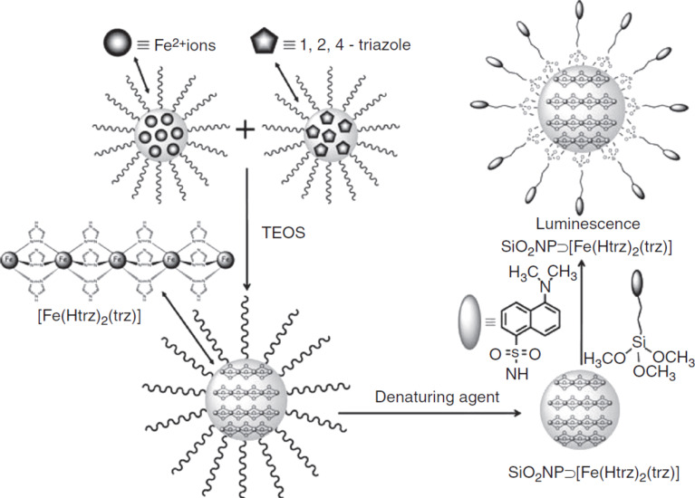
Synthesis route and schematic representation of the luminescent, SCO, SiO2 nanoparticles. Reproduced with permission from [21], copyright 2011 Wiley-VCH.
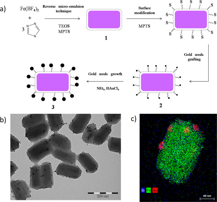
a) Schematic overview of the formation of the nanocomposite, gold-decorated SCO–SiO2 nanoparticles. b) TEM and c) STEM–EDX images of the particles. Adapted with permission from [23], copyright 2014 The Royal Society of Chemistry.
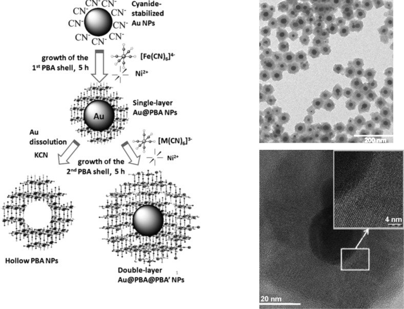
Schematic representation of single layer Au@PBA nanoparticles, double layer Au@PBA@PBA core–shell NPs, and hollow PBA NPs. On the right, TEM and HRTEM images of the Au@KNiFe NPs. Adapted with permission from [25], copyright 2014 Wiley-VCH.
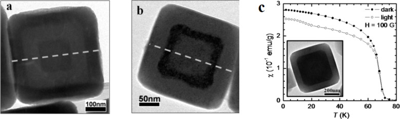
HRTEM images of core–multishell PBA nanoparticles a) RbCoFe@KNiCr@RbCoFe and b) KNiCr@RbCoFe@KNiCr, and c) shows the field-cooled magnetic susceptibility as a function of temperature before and after light irradiation of RbCoFe@KNiCr. Adapted with permission from [27], copyright 2011 American Chemical Society.
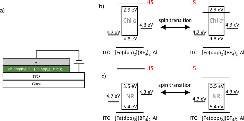
a) Architecture of the OLED device constructed by Matsuda et al. [28]. b) A schematic representation of the mechanism proposed for the EL, on/off switching, based on an energy level diagram of a device using Chl a and [Fe(dpp)2](BF)4. c) Energy level diagram for an analog device but employing NR as the emitting material [30]. Adapted with permission from [28] and [30], copyright 2008 and 2013 Elsevier.
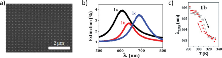
a) SEM image of a gold nanorod array with 200 nm pitch. b) Extinction spectra of three nanorod arrays with different aspect ratios. c) Plasmon resonance shift associated with the spin crossover of a 60 nm thin film deposited onto the nano-dot array displayed in a) as a function of temperature. Adapted with permission from [34], copyright 2013 The Royal Society of Chemistry.
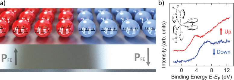
a) Schematic view of the molecular memory proposed by Zhang et al. At low temperatures, the spin state is determined by the polarization of the ferroelectric substrate. If the substrate is poled “up”, the SCO molecules will remain HS; conversely, the SCO molecules will adopt the LS form for a substrate poled “down”. b) Inverse photoemission spectrum at 170 K for a 25 molecule thick layer of [Fe(H2B(pz)2(bipy)] deposited on PVDF–TrFE poled “up” (red) and “down” (blue). Each spectrum corresponds to the characteristic signature of the complex in the HS and LS form, respectively. Adapted with permission from [35], copyright 2014 The Royal Society of Chemistry.
Thermal SCO curves for different thicknesses of an inactive HS shell, calculated with a compressible Ising-like model with harmonic potential. Top panel: core–shell system with an SCO active core and an inactive HS shell. Adapted with permission from [40], copyright 2013 American Physical Society.
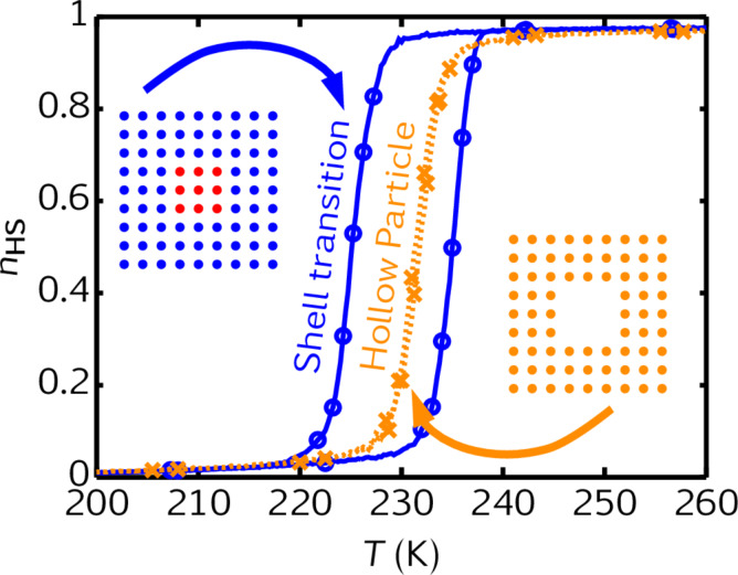
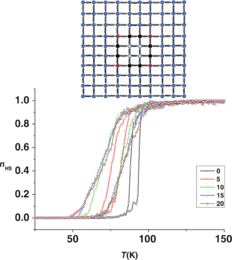
Comparison between the thermal SCO curves of a 9 × 9 hollow particle with a 3 × 3 hole and a 9 × 9 shell surrounding a 3 × 3 active core. Adapted with permission from [41], copyright 2014 Elsevier.
References
Publication types
LinkOut - more resources
Full Text Sources
Other Literature Sources