. 2015 Mar 11;27(10):1668-75.
doi: 10.1002/adma.201404772. Epub 2015 Jan 2.

Toward a new generation of electrically controllable hygromorphic soft actuators

Affiliations

Toward a new generation of electrically controllable hygromorphic soft actuators

Silvia Taccola et al. Adv Mater. .

Abstract

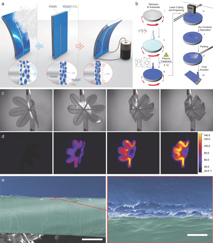
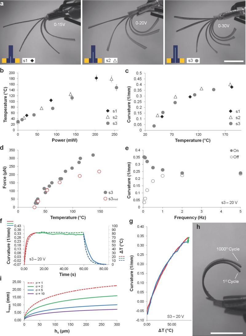
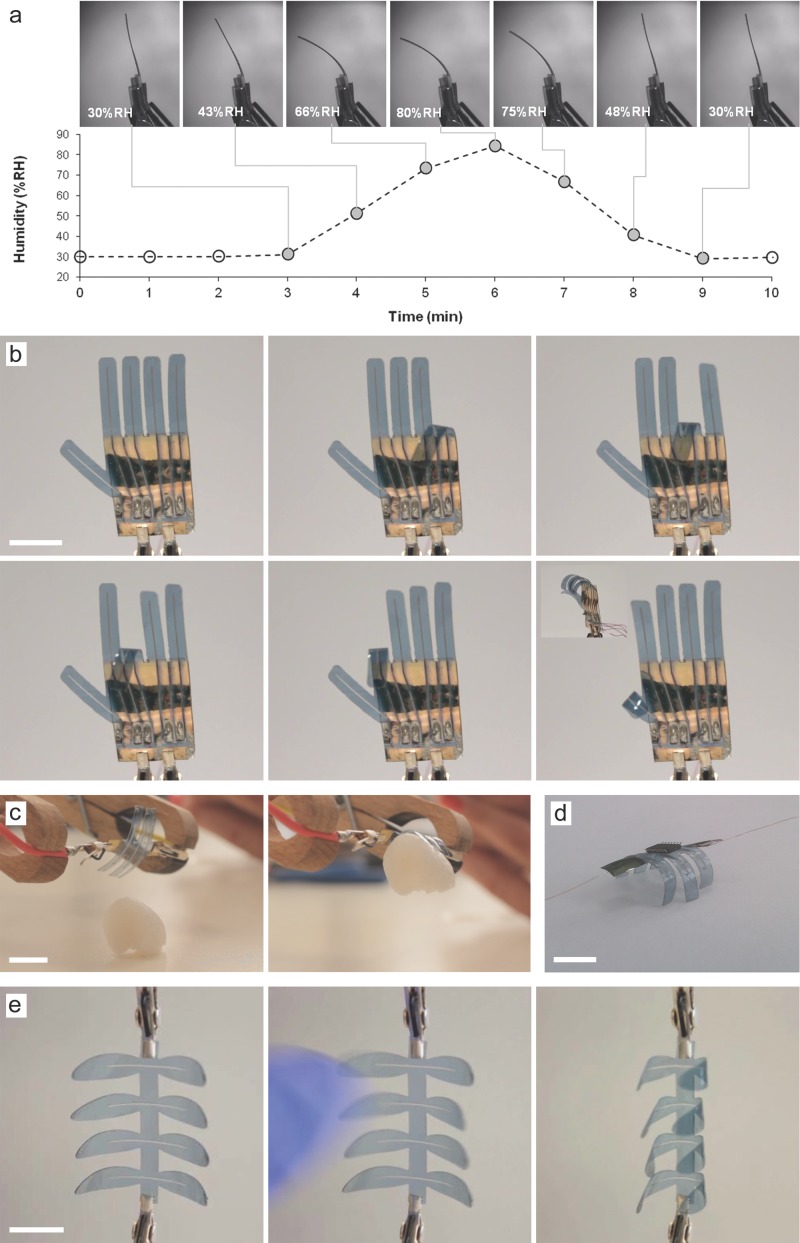
An innovative processing strategy for fabricating soft structures that possess electric- and humidity-driven active/passive actuation capabilities along with touch- and humidity-sensing properties is reported. The intrinsically multifunctional material comprises an active thin layer of poly(3,4-ethylenedioxythiophene):poly-(styrene sulfonate) in a double-layered structure with a silicone elastomer and provides an opportunity toward developing a new class of smart structures for soft robotics.

Keywords: conducting polymers; hygromorphic materials; poly(3,4ethylenedioxythiophene):polystyrene sulfonate; soft actuators; stimuli-responsive materials.


Figures

Figure 1
Figure 1
a) Schematic representation of the working principle behind the actuators based on the sorption/desorption of environmental moisture: beginning from the original position (central), in which the actuator is in equilibrium with its environment, the application of an electric current drives a contraction of the PEDOT:PSS layer due to Joule-heating-induced water desorption, which subsequently induces a bending motion toward the PEDOT:PSS layer (right); in the reverse process, as the environmental moisture content increases, the actuator bends from its original position toward the PDMS layer due to the sorption of water until a new equilibrium is established (left). b) Overview of the actuator fabrication process: (i) silanization of the silicon wafer; (ii) deposition of the PDMS layer by spin coating; (iii) air plasma treatment and deposition of PEDOT:PSS (12 layers) by spin coating; (iv) laser cutting and patterning; (v) deposition of gold electrodes by DC sputtering; and (vi) peeling of the bilayer. c) Actuation movement of an electrically driven flower-shaped actuator and corresponding thermal images. d) When a voltage is applied between the electrodes, the pattern drives the flow of current along each petal, which allows the structure to fold (see also Video S3, Supporting Information). e) Scanning electron microscopy (SEM) images (40° tilted view) of a cross section of the PEDOT:PSS/PDMS bilayer, which was cut using a razor blade. The magnification of the left image is 800× (scale bar represents 50 μm), and the magnification of the right image is 80 000× (scale bar represents 500 nm). The image was postcolorized: the PDMS layer is green, and the PEDOT:PSS layer is blue.
Figure 2
Figure 2
a) The superpositions of images taken at different input voltages for s1, s2, and s3 highlight the difference between the bending behaviors of the samples. Actuator surface temperature versus applied power. b) and curvature versus temperature c) for the three samples. d) Measured blocking force at different temperatures for sample s3 compared with the theoretical force (s3mod). e) On/Off curvature of sample s3 powered with a square wave voltage with an amplitude of 20 V at different frequencies. Time profiles of surface temperature, curvature. f), and corresponding temperature dependence of curvature g) of sample s3 in response to a step input voltage of 20 V. h) Superposition of images taken for sample s3 before and after 1000 cycles of actuation with a square wave input voltage with a frequency of 0.05 Hz and amplitude of 20 V. All scale bars represent 5 mm. i) Actuator preliminary design chart (example): for a given thickness hs of the PDMS layer, each curve shows the maximum actuator length Lmax that should not be exceeded to ensure Fb > σW, where σ is a targeted value. This chart shows that actuation is more effective for sample lengths that are less than ≈1 cm.
Figure 3
Figure 3
a) Passive bending motion of a beam caused by variations in the RH level in a humidity-controlled chamber at T = 30 °C (side view, PEDOT:PSS layer on the right). b) Hand-shaped actuator with individually addressable fingers. c) A 6-finger gripper prototype used to demonstrate the ability to lift a lightweight object (a piece of polystyrene foam). d) and to stand up on a plane. e) A leaf-shaped actuator (left) as a multifunctional system able to respond to touch stimuli (central) by closing its leaves (right). All scale bars represent 1 cm.

References

    1. Minko S. Responsive Polymer Materials: Design and Applications. Ames, IA, USA: Wiley-Blackwell; 2006. p. 101.
    1. Cohen Stuart MA, Huck WTS, Genzer J, Müller M, Ober C, Stamm M, Sukhorukov GB, Szleifer I, Tsukruk VV, Urban M, Winnik F, Zauscher S, Luzinov I, Minko Sergiy. Nat. Mater. 2010;9 - PubMed
    1. Jager EWH, Smela E, Inganäs O. Science. 2000;290:1540. - PubMed
    1. Carpi F, Smela E. Biomedical Applications of Electroactive Polymer Actuators. Chichester, UK: John Wiley & Sons; 2009.
    1. Otero TF. Polym. Rev. 2013;53

Publication types