. 2014 Dec 11:7:43.
doi: 10.3389/fneng.2014.00043. eCollection 2014.

A low-cost programmable pulse generator for physiology and behavior

Affiliations

A low-cost programmable pulse generator for physiology and behavior

Joshua I Sanders et al. Front Neuroeng. .

Abstract

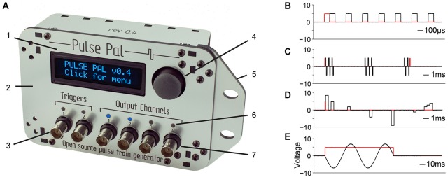
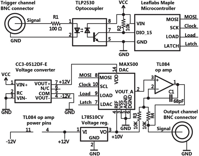
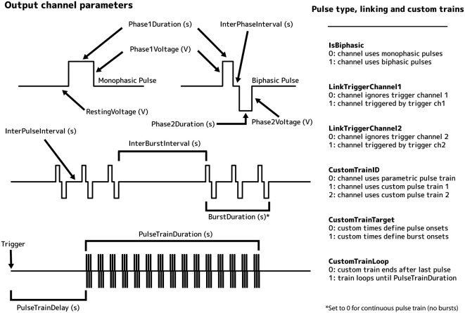
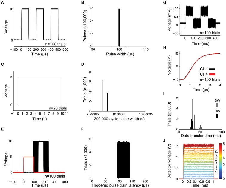
Precisely timed experimental manipulations of the brain and its sensory environment are often employed to reveal principles of brain function. While complex and reliable pulse trains for temporal stimulus control can be generated with commercial instruments, contemporary options remain expensive and proprietary. We have developed Pulse Pal, an open source device that allows users to create and trigger software-defined trains of voltage pulses with high temporal precision. Here we describe Pulse Pal's circuitry and firmware, and characterize its precision and reliability. In addition, we supply online documentation with instructions for assembling, testing and installing Pulse Pal. While the device can be operated as a stand-alone instrument, we also provide application programming interfaces in several programming languages. As an inexpensive, flexible and open solution for temporal control, we anticipate that Pulse Pal will be used to address a wide range of instrumentation timing challenges in neuroscience research.

Keywords: Pulse Pal; arduino; maple; open source; optogenetics; pulse generator; stimulator; timing.


Figures

Figure 1
Figure 1
Pulse Pal is a programmable pulse train generator. (A) Pulse Pal front view, illustrating front panel features. 1: High contrast oLED screen permits programming with thumb joystick for stand-alone use. 2: Custom laser-cut acrylic enclosure. 3: Two optically isolated digital trigger channels. 4: Thumb joystick. 5: Rack-mount wing. 6: Channel activity indicators illuminate when channel voltage is not the set resting voltage (i.e., during a pulse). 7: Each of four analog output channels can be programmed with independent pulse trains and linked to either trigger channel. (B–E) Example pulse trains in black, acquired with an oscilloscope (see methods). Trigger voltage traces are shown in red. (B) A Pulse Pal output channel configured to deliver a train of 5 V, 100 µs square pulses with 200 µs intervals. (C) A train of biphasic +/−5 V 100 µs pulses, gated programmatically to produce pulse bursts. Trigger channel mode set to “toggle” aborts the ongoing pulse train in mid-burst when a second pulse arrives. (D) A train of 500 µs pulses with custom onset times and voltages. Pulses with consecutive onset times merge to form more complex waveforms (right). (E) A train of consecutive 100 µs pulses, whose voltages and onset times were configured to generate one period of a sine waveform. The output channel uses “loop mode”, to repeat the sine waveform until a parametrically specified pulse train end. The trigger channel mode was set to “pulse gated” mode, to abort the pulse train when its voltage returned low.
Figure 2
Figure 2
Schematic of the basic circuit for triggering and pulse generation. The schematic for Pulse Pal’s trigger and stimulation circuitry is shown for a single trigger and output channel, omitting duplicate circuitry for all other channels. Thumb joystick, oLED display, indicator LED and EEPROM connections with the microcontroller were omitted for clarity.
Figure 3
Figure 3
Illustration of output channel parameters.
Figure 4
Figure 4
Measurements of precision and reliability. (A–B) For a train of three 100 µs pulses with 100 µs pulse intervals: (A) the first 100 waveforms captured with the oscilloscope are shown superimposed, and (B) distribution of pulse widths measured from 100,000 3-pulse trains, captured as in (A). (C–D) For a train of a single 10 s pulse: (C) waveforms from the first 20 trials and (D) 10,000 pulse widths. (E) The latency of a pulse train of one 10 V, 100 µs pulse captured from an output channel (shown in black for 100 trials) was measured with respect to a 5 V, 100 µs pulse delivered to a linked trigger channel (shown in red). (F) Distribution of pulse train latencies for 100,000 trials. (G) 100 superimposed 78.1 mV pulses, showing the smallest possible increment of the digital to analog converter and channel noise caused by digital feed-through from the SPI bus. (H) Simultaneous and rapid settling of the voltage on channels 1 and 4 when delivering a +10 V pulse from a resting voltage of −10 V. (I) USB transfer time is shown for a 5,006 byte message containing pulse times and voltages for a 1,000-pulse custom train. Transfer time was measured with hardware (HW, black; using firmware modified to indicate transmission start and end with a voltage pulse) and software (SW, gray; using the controlling computer’s clock). (J) 1 ms pulses of light, produced by controlling a blue diode laser with Pulse Pal, converted to voltage with an Si transimpedence amplified photodetector (PDA10A, ThorLabs), and captured with an oscilloscope. Single traces are shown for voltage pulses ranging from 78 mV to 5 V in amplitude.

References

    1. Berényi A., Belluscio M., Mao D., Buzsáki G. (2012). Closed-loop control of epilepsy by transcranial electrical stimulation. Science 337, 735–737. 10.1126/science.1223154 - DOI - PMC - PubMed
    1. Bisley J. W., Zaksas D., Pasternak T. (2001). Microstimulation of cortical area MT affects performance on a visual working memory task. J. Neurophysiol. 85, 187–196. - PubMed
    1. Boyden E. S., Zhang F., Bamberg E., Nagel G., Deisseroth K. (2005). Millisecond-timescale, genetically targeted optical control of neural activity. Nat. Neurosci. 8, 1263–1268. 10.1038/nn1525 - DOI - PubMed
    1. Brainard D. H. (1997). The psychophysics toolbox. Spat. Vis. 10, 433–436. 10.1163/156856897x00357 - DOI - PubMed
    1. Brunton B. W., Botvinick M. M., Brody C. D. (2013). Rats and humans can optimally accumulate evidence for decision-making. Science 340, 95–98. 10.1126/science.1233912 - DOI - PubMed