. 2015 Feb 7;60(3):1047-67.
doi: 10.1088/0031-9155/60/3/1047. Epub 2015 Jan 14.

An evaluation of three commercially available metal artifact reduction methods for CT imaging

Affiliations

An evaluation of three commercially available metal artifact reduction methods for CT imaging

Jessie Y Huang et al. Phys Med Biol. .

Abstract

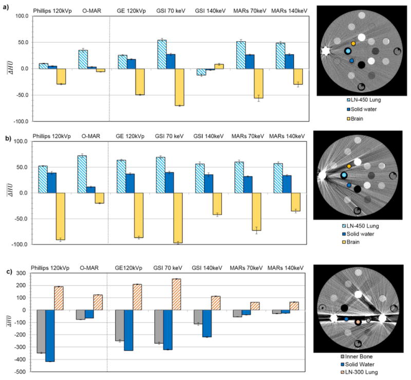
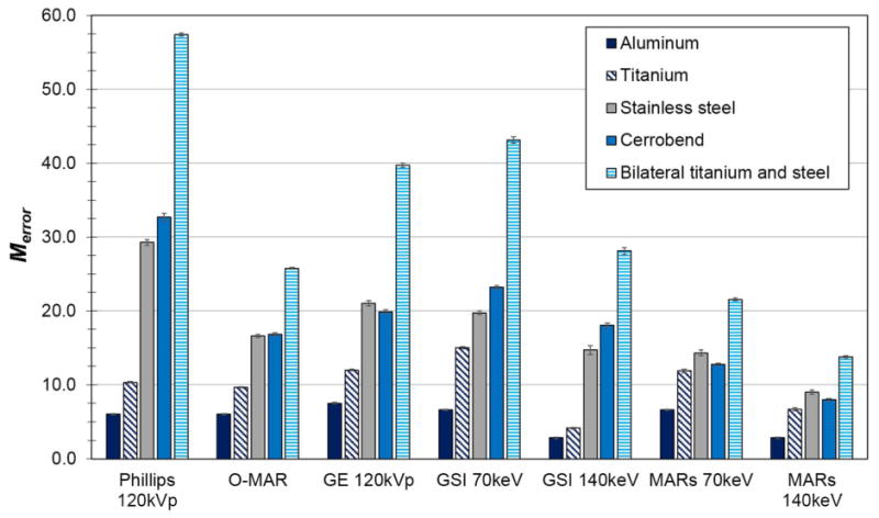
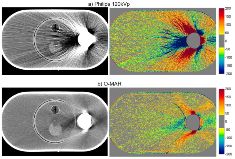
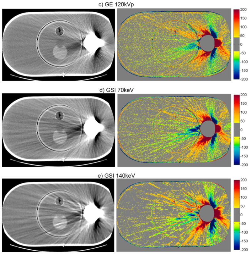
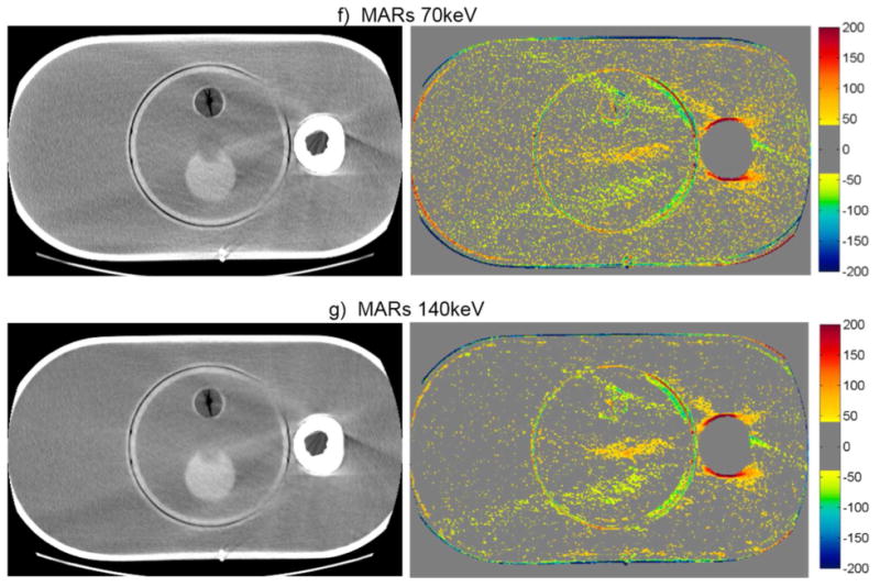
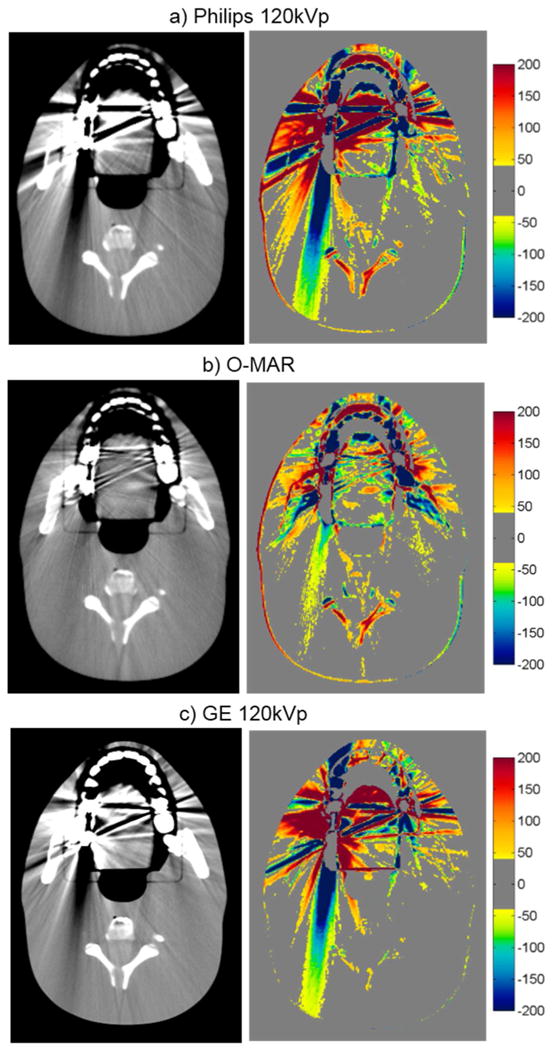
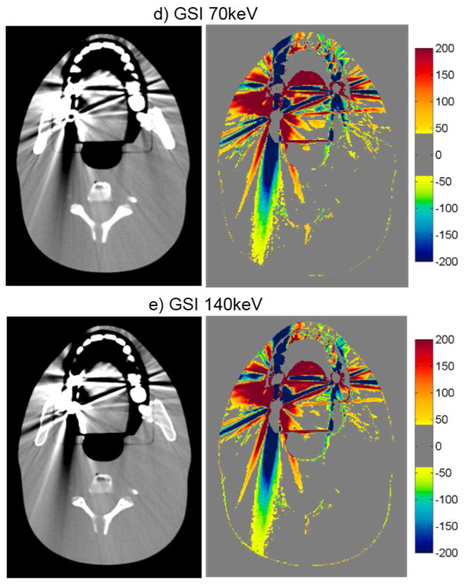
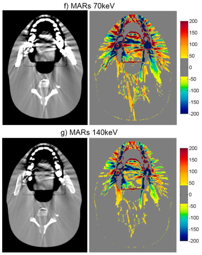
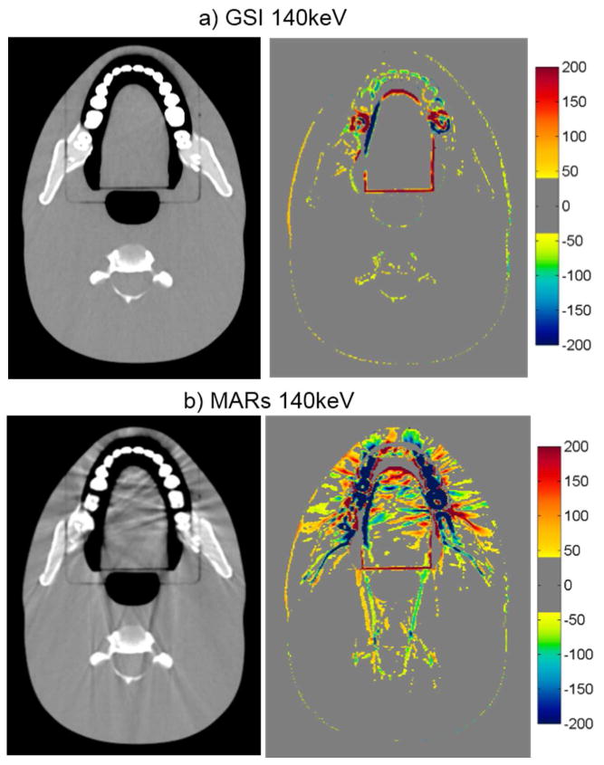
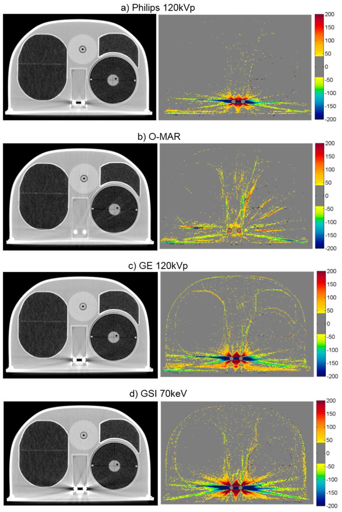
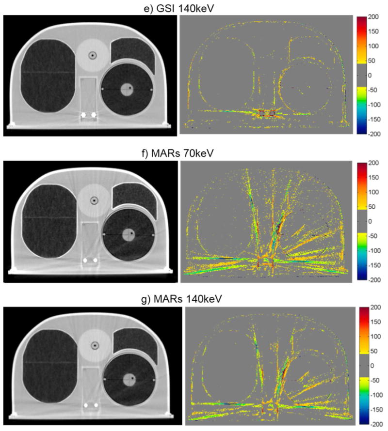
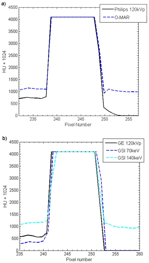
Three commercial metal artifact reduction methods were evaluated for use in computed tomography (CT) imaging in the presence of clinically realistic metal implants: Philips O-MAR, GE's monochromatic gemstone spectral imaging (GSI) using dual-energy CT, and GSI monochromatic imaging with metal artifact reduction software applied (MARs). Each method was evaluated according to CT number accuracy, metal size accuracy, and streak artifact severity reduction by using several phantoms, including three anthropomorphic phantoms containing metal implants (hip prosthesis, dental fillings and spinal fixation rods). All three methods showed varying degrees of success for the hip prosthesis and spinal fixation rod cases, while none were particularly beneficial for dental artifacts. Limitations of the methods were also observed. MARs underestimated the size of metal implants and introduced new artifacts in imaging planes beyond the metal implant when applied to dental artifacts, and both the O-MAR and MARs algorithms induced artifacts for spinal fixation rods in a thoracic phantom. Our findings suggest that all three artifact mitigation methods may benefit patients with metal implants, though they should be used with caution in certain scenarios.


Figures

Figure 1
Figure 1
ΔHU¯ for select tissue substitue regions of interest in the RMI phantom scanned with (a) a unilateral titanium plug, (b) a unilateral stainless steel plug, and (c) bilateral stainless steel and titanium plugs. ΔHU¯ are grouped by imaging techniqe, including uncorrected imaging methods (120kVp) as well as the metal artifact reduction methods. For each plot, a CT image (Philips 120kVp protocol, WL=0, WW=500) on the right shows the location of the tissue substitute inserts for which ΔHU¯ is plotted and the position of metal inserts in the phantom. Error bars indicate the standard error of the mean for three repeated scans.
Figure 2
Figure 2
Merror, the fraction of bad pixels in the phantom image multiplied by the mean absolute CT number error of the bad pixels, for various imaging techniques and metal scan configurations of the RMI phantom.
Figure 3
Figure 3
CT images of the pelvic phantom with hip prosthesis (WL=0, WW=500), side by side with the corresponding CT number difference maps between the baseline and the metal scans of the phantom for uncorrected imaging methods (“Philips 120kVp” and “GE 120kVp”) and artifact mitigation methods (“O-MAR”, “GSI”, and “MARs”).This image intersects the femoral head portion of the prosthesis.
Figure 3
Figure 3
CT images of the pelvic phantom with hip prosthesis (WL=0, WW=500), side by side with the corresponding CT number difference maps between the baseline and the metal scans of the phantom for uncorrected imaging methods (“Philips 120kVp” and “GE 120kVp”) and artifact mitigation methods (“O-MAR”, “GSI”, and “MARs”).This image intersects the femoral head portion of the prosthesis.
Figure 4
Figure 4
CT images of the head phantom with dental fillings (WL=0, WW=500), side by side with the corresponding CT number difference maps between the baseline and the metal scans of the phantom for uncorrected imaging methods (“Philips 120kVp” and “GE 120kVp”) and artifact mitigation methods (“O-MAR”, “GSI”, and “MARs”).
Figure 4
Figure 4
CT images of the head phantom with dental fillings (WL=0, WW=500), side by side with the corresponding CT number difference maps between the baseline and the metal scans of the phantom for uncorrected imaging methods (“Philips 120kVp” and “GE 120kVp”) and artifact mitigation methods (“O-MAR”, “GSI”, and “MARs”).
Figure 5
Figure 5
Grayscale CT images of the head phantom with dental fillings (WL=0, WW=500), side by side with the corresponding CT number difference maps between the baseline and the metal scans of the phantom for a) GSI 140keV and b) MARs 140keV imaging. Shown is an image of the head phantom that does not contain any portion of the metal fillings, illustrating out-of-plane artifacts introduced by the MARs algorithm.
Figure 6
Figure 6
Grayscale CT images of the anthropomorphic thoracic phantom with titanium spinal rods (WL = -250, WW = 1250), side by side with the corresponding CT number difference maps between the baseline and the metal scans of the phantom for uncorrected imaging methods (“Philips 120kVp” and “GE 120kVp”) and artifact mitigation methods (“O-MAR”, “GSI”, and “MARs”).
Figure 6
Figure 6
Grayscale CT images of the anthropomorphic thoracic phantom with titanium spinal rods (WL = -250, WW = 1250), side by side with the corresponding CT number difference maps between the baseline and the metal scans of the phantom for uncorrected imaging methods (“Philips 120kVp” and “GE 120kVp”) and artifact mitigation methods (“O-MAR”, “GSI”, and “MARs”).
Figure 7
Figure 7
Horizonal pixel intensity profiles taken across one of the titanium rods scanned with the thoracic phantom for a) O-MAR, b) GSI imaging (“GSI 70keV” and “GSI 140keV”), and c) GSI imaging with MARs applied (“MARs 70keV” and “MARs 140keV”). The corresponding uncorrected imaging methods (“Philips 120kVp” and “GE 120kVp”) are also shown for comparison.
Figure 7
Figure 7
Horizonal pixel intensity profiles taken across one of the titanium rods scanned with the thoracic phantom for a) O-MAR, b) GSI imaging (“GSI 70keV” and “GSI 140keV”), and c) GSI imaging with MARs applied (“MARs 70keV” and “MARs 140keV”). The corresponding uncorrected imaging methods (“Philips 120kVp” and “GE 120kVp”) are also shown for comparison.

References

    1. Metal Artifact Reduction for Orthopedic Implants (O-MAR) White Paper. Philips Healthcare; 2012.
    1. Barrett JF, Keat N. Artifacts in CT: recognition and avoidance. Radiographics : a review publication of the Radiological Society of North America, Inc. 2004;24:1679–91. - PubMed
    1. Bazalova M, Beaulieu L, Palefsky S, Verhaegena F. Correction of CT artifacts and its influence on Monte Carlo dose calculations. Med Phys. 2007;34:2119–32. - PubMed
    1. Boas FE, Fleischmann D. Evaluation of Two Iterative Techniques for Reducing Metal Artifacts in Computed Tomography. Radiology. 2011;259:894–902. - PubMed
    1. Brook OR, Gourtsoyianni S, Brook A, Mahadevan A, Wilcox C, Raptopoulos V. Spectral CT with metal artifacts reduction software for improvement of tumor visibility in the vicinity of gold fiducial markers. Radiology. 2012;263:696–705. - PubMed

Publication types