. 2015 Mar 6;12(104):20141164.
doi: 10.1098/rsif.2014.1164.

A steering mechanism for phototaxis in Chlamydomonas

Affiliations

A steering mechanism for phototaxis in Chlamydomonas

Rachel R Bennett et al. J R Soc Interface. .

Abstract

Chlamydomonas shows both positive and negative phototaxis. It has a single eyespot near its equator, and as the cell rotates during the forward motion, the light signal received by the eyespot varies. We use a simple mechanical model of Chlamydomonas that couples the flagellar beat pattern to the light intensity at the eyespot to demonstrate a mechanism for phototactic steering that is consistent with observations. The direction of phototaxis is controlled by a parameter in our model, and the steering mechanism is robust to noise. Our model shows switching between directed phototaxis when the light is on and run-and-tumble behaviour in the dark.

Keywords: cell locomotion; flagella; phototaxis.


Figures

Figure 1.
Figure 1.
(a) The three-sphere model: each flagellum is represented by a sphere, shown in blue, moving around a circular trajectory and has phase ϕc,t. Each sphere is driven by a phase-dependent tangential force. A third sphere, shown in dark green, represents the cell body, and the red spot indicates the position of the eyespot. The green underlay is a schematic of the real cell, and the orange arrows show incoming light. (b) The cell rotates about the formula image-
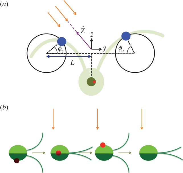
axis so when it swims perpendicular to the light direction (orange arrows), the light signal varies. For half the cycle, the eyespot is in the dark, then when the eyespot crosses the horizon line the light signal varies as formula image, where formula image is the angle between the outward normal from the eyespot and the direction towards light. (Online version in colour.)
Figure 2.
Figure 2.
Example trajectories of the cell with alternating between light and dark shown in terms of length scale L, where 2L is the average distance between flagella beads, and time scale tc = 6πηaL/F0, where η is viscosity of water and a is radius of the beads. The parameters used are p =−1, Ib = 0.1, I0 = 0.1, σ = 4.7 × 10⁻³, and the initial condition is θ0 = π/2. (a) For 0 < t < T/3 and 2/3T < t < T, the light is on (red), where T is the total time of the trajectory. For T/3 < t < 2/3T, the cell is in the dark (blue) and shows run-and-tumble behaviour. The orange arrow shows the direction of the incoming light, and the green spot (not to scale) shows the initial position of the cell. The inset shows the helical shape of the trajectory. (b) An example trajectory where the light is off for t < T/2, and the light is on for t > T/2. The cell is in the dark for twice as long as in (a) and we see twice as many tumbles. (c,d) (red/blue) Curvature, κ, of the trajectory shown in (a) and (b), respectively, when we average over the helical motion. The large peaks in the curvature during darkness correspond to tumbles. (green) Phase difference, δ, of the beating flagella during darkness. The black stars highlight the peaks in curvature. (Online version in colour.)
Figure 3.
Figure 3.
Trajectories of the cell with different values of coupling strength p projected into the YZ plane, where t/tc ∈ [0, 180]. Blue circles, p = 0.5; purple squares, p = 0.8; green diamonds, p = 1.2; red triangles, p = 1.8. The cell is initially oriented in the formula image-
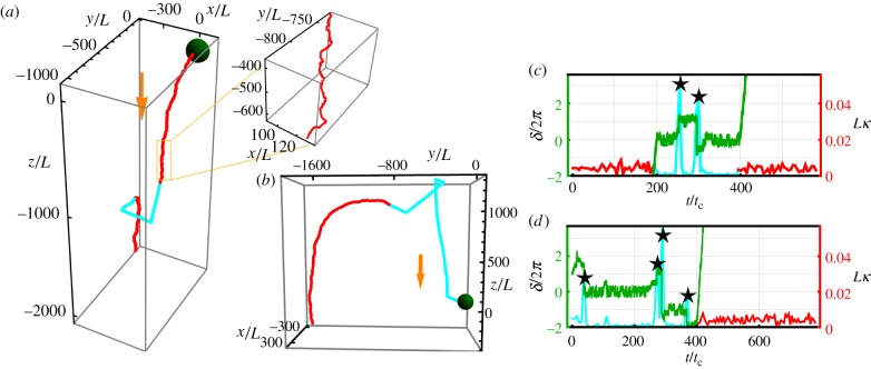
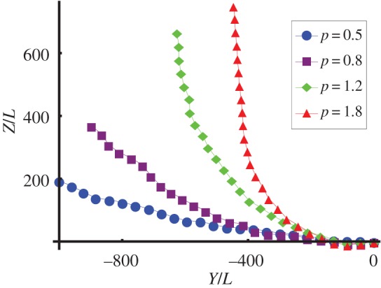
direction and steers towards the light coming in from the formula image-direction. At formula image the cells with p = 1.2 and p = 1.8 have oriented towards the light, but the cells with p = 0.5 and p = 0.8 are still slowly bending towards the light. (Online version in colour.)
Figure 4.
Figure 4.
(a) Diagram of helix showing phases corresponding to those marked in (c). (b) A change in γ is facilitated by the helix axis changing direction by δγ. The purple dashed line shows the new cell axis after γγ + δγ. (c) The effect of changes in γ on the angle χ depends on the phase of the cell: δχ = δγsinφ. The red triangle and purple square mark the positions φ = 0 and i = π, respectively. When the cell has position φ ∈ (0, π), an increase (decrease) in γ causes the helix axis to bend away from (towards) the light and a corresponding decrease (increase) in γ when φ ∈ (π, 2π) also causes the helix axis to bend away from (towards) the light. The incoming light is marked by the pink arrow, and the blue arrows show the direction that the cell travels along the helix. The dashed lines at φ = π/2 and φ = 3π/2 show the new direction of the helix axis if γ increases and decreases, respectively, by δγ at these positions. (Online version in colour.)

References

    1. Berg HC, Purcell EM. 1977. Physics of chemoreception. Biophys. J. 20, 193–219. (10.1016/S0006-3495(77)85544-6) - DOI - PMC - PubMed
    1. Block SM, Segall JE, Berg HC. 1982. Impulse responses in bacterial chemotaxis. Cell 31, 215–226. (10.1016/0092-8674(82)90421-4) - DOI - PubMed
    1. Segall JE, Block SM, Berg HC. 1986. Temporal comparisons in bacterial chemotaxis. Proc. Natl Acad. Sci. USA 80, 8987–8991. (10.1073/pnas.83.23.8987) - DOI - PMC - PubMed
    1. Friedrich BM, Jülicher F. 2009. Steering chiral swimmers along noisy helical paths. Phys. Rev. Lett. 103, 068102 (10.1103/PhysRevLett.103.068102) - DOI - PubMed
    1. Polin M, Tuval I, Drescher K, Gollub JP, Goldstein RE. 2009. Chlamydomonas swims with two ‘gears’ in a eukaryotic version of run-and-tumble locomotion. Science 325, 487–490. (10.1126/science.1172667) - DOI - PubMed

Publication types

LinkOut - more resources