. 2014 Dec 29;22(26):32082-97.
doi: 10.1364/OE.22.032082.

Parallel ptychographic reconstruction

Parallel ptychographic reconstruction

Youssef S G Nashed et al. Opt Express. .

Abstract

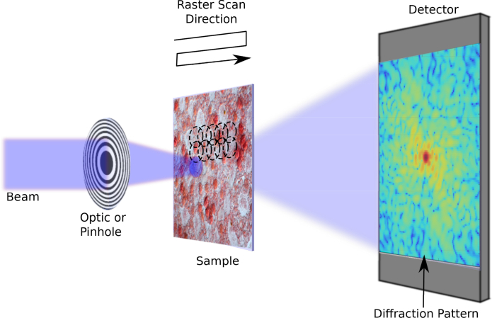
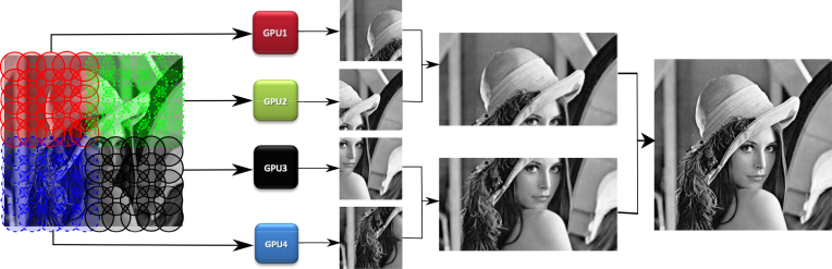
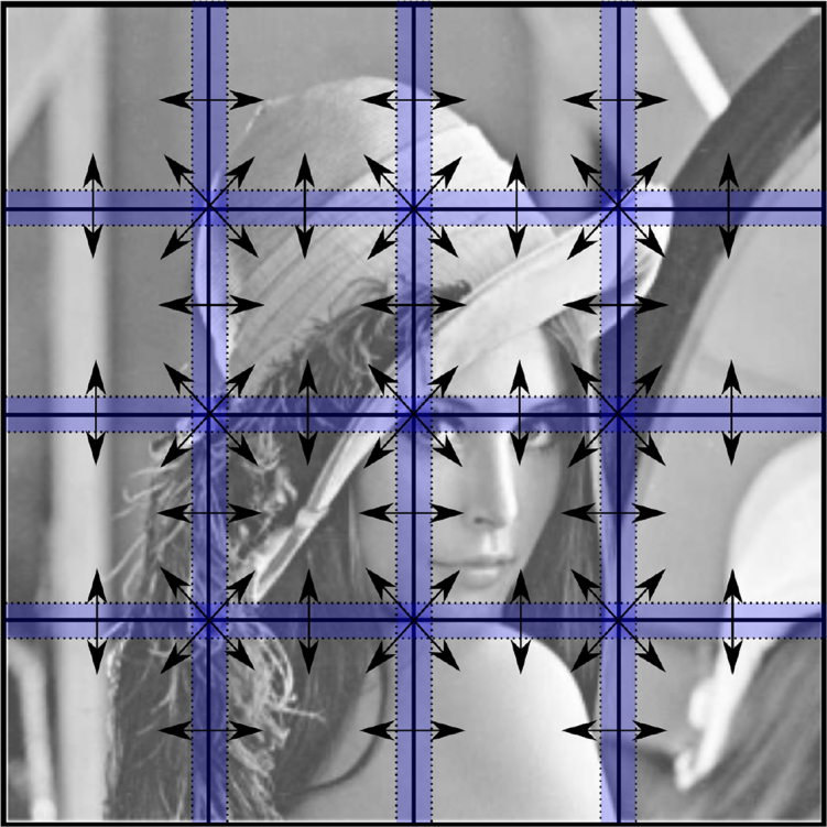
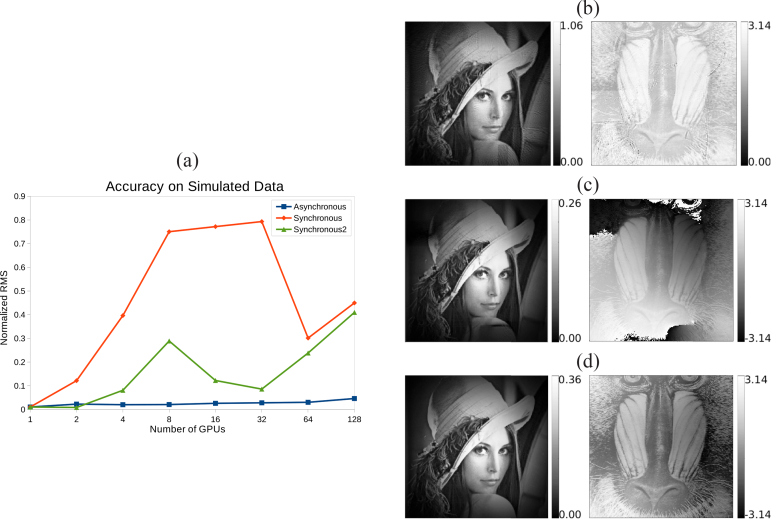
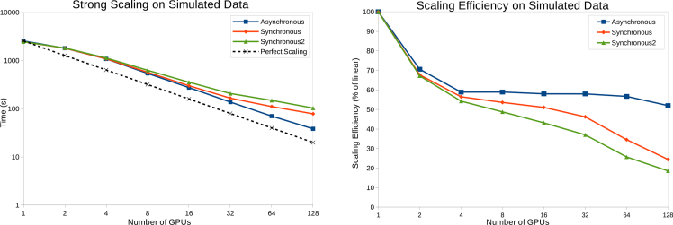
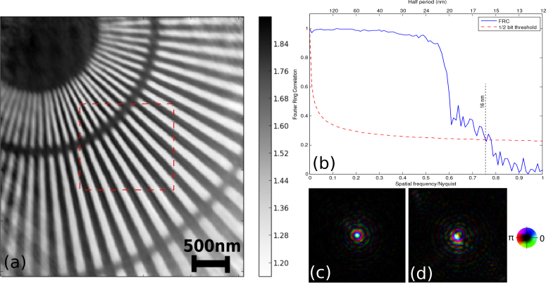
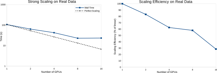
Ptychography is an imaging method whereby a coherent beam is scanned across an object, and an image is obtained by iterative phasing of the set of diffraction patterns. It is able to be used to image extended objects at a resolution limited by scattering strength of the object and detector geometry, rather than at an optics-imposed limit. As technical advances allow larger fields to be imaged, computational challenges arise for reconstructing the correspondingly larger data volumes, yet at the same time there is also a need to deliver reconstructed images immediately so that one can evaluate the next steps to take in an experiment. Here we present a parallel method for real-time ptychographic phase retrieval. It uses a hybrid parallel strategy to divide the computation between multiple graphics processing units (GPUs) and then employs novel techniques to merge sub-datasets into a single complex phase and amplitude image. Results are shown on a simulated specimen and a real dataset from an X-ray experiment conducted at a synchrotron light source.


Figures

Fig. 1
Fig. 1
Simplified ptychography experiment setup showing a Cartesian grid used for the overlapping raster scan positions.
Fig. 2
Fig. 2
GPU memory layout of a 2D M×N matrix. The gray area represents the aligned matrix zero padding, where W = warp size (32 threads on most devices). The padded area is always ignored in matrix operations. CUDA blocks operate on matrix slices of size s such as the region outlined by the dashed red line. Memory requests for a row of the padded matrix are served by a single cache line.
Fig. 3
Fig. 3
The diffraction patterns are subdivided and distributed among available GPUs. Pairwise stitching is performed on the separate reconstructions attained by phase retrieval.
Fig. 4
Fig. 4
Object array sharing through neighborhood exchange between 16 GPUs. The overlap (halo), highlighted in blue, is defined in terms of additional scan points assigned to each GPU sub-dataset.
Fig. 5
Fig. 5
(a) Normalized RMS error of final reconstructions achieved by different GPU configurations using the asynchronous, synchronous, and synchronous with halo=2 implementations. (b) Magnitude and phase of the object wavefront retrieved from simulated data using the asynchronous version and 128 GPUs. (c) Magnitude and phase of the object wavefront retrieved from simulated data using the synchronous version and 32 GPUs. (d) Magnitude and phase of the object wavefront retrieved from simulated data using the synchronous version, 32 GPUs, and a halo region of 2 additional scan point rows and columns.
Fig. 6
Fig. 6
Performance plots on synthetic data. Left: Total running time (in seconds) of different GPU configurations. Right: The scaling efficiency plotted as a percentage of linear scaling.
Fig. 7
Fig. 7
(a) Phase image of the reconstructed object transmission function, with the 1 μm×1 μm scan region highlighted in red. (b) Fourier ring correlation (FRC) plot showing a spatial resolution of 16 nm in the phase of the exit surface wave. (c,d) The recovered illumination function of two probe modes.
Fig. 8
Fig. 8
Performance plots on real data. Left: Total running time (in seconds) of different GPU configurations. Right: The scaling efficiency plotted as a percentage of linear scaling.

References

    1. Born M., Wolf E., Principles of Optics: Electromagnetic Theory of Propagation, Interference and Diffraction of Light (CUP Archive, 1999).10.1017/CBO9781139644181 - DOI
    1. Hell S. W., Wichmann J., “Breaking the diffraction resolution limit by stimulated emission: stimulated-emission-depletion fluorescence microscopy,” Opt. Lett. 19, 780–782 (1994).10.1364/OL.19.000780 - DOI - PubMed
    1. Betzig E., Patterson G. H., Sougrat R., Lindwasser O. W., Olenych S., Bonifacino J. S., Davidson M. W., Lippincott-Schwartz J., Hess H. F., “Imaging intracellular fluorescent proteins at nanometer resolution,” Science 313, 1642–1645 (2006).10.1126/science.1127344 - DOI - PubMed
    1. Rust M. J., Bates M., Zhuang X., “Sub-diffraction-limit imaging by stochastic optical reconstruction microscopy (storm),” Nature Methods 3, 793–796 (2006).10.1038/nmeth929 - DOI - PMC - PubMed
    1. Hell S. W., “Far-field optical nanoscopy,” Science 316, 1153–1158 (2007).10.1126/science.1137395 - DOI - PubMed

Publication types

MeSH terms