. 2015 Jan 13;9(1):016501.
doi: 10.1063/1.4905840. eCollection 2015 Jan.

3D printed microfluidic devices with integrated valves

Affiliations

3D printed microfluidic devices with integrated valves

Chad I Rogers et al. Biomicrofluidics. .

Abstract

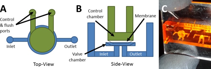
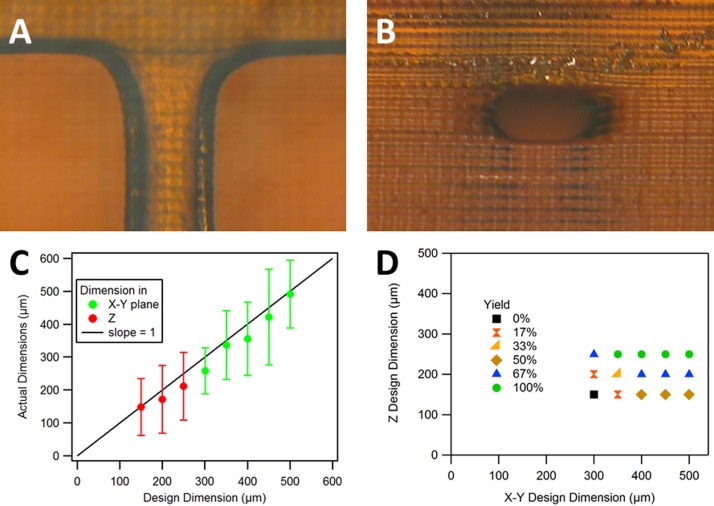
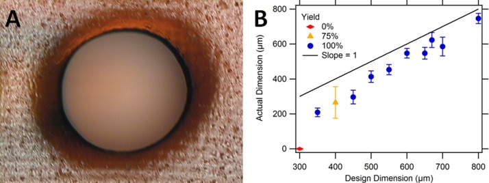
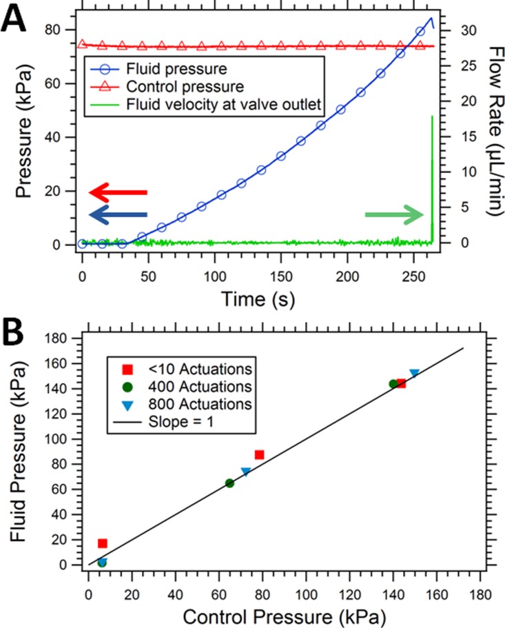
We report the successful fabrication and testing of 3D printed microfluidic devices with integrated membrane-based valves. Fabrication is performed with a low-cost commercially available stereolithographic 3D printer. Horizontal microfluidic channels with designed rectangular cross sectional dimensions as small as 350 μm wide and 250 μm tall are printed with 100% yield, as are cylindrical vertical microfluidic channels with 350 μm designed (210 μm actual) diameters. Based on our previous work [Rogers et al., Anal. Chem. 83, 6418 (2011)], we use a custom resin formulation tailored for low non-specific protein adsorption. Valves are fabricated with a membrane consisting of a single build layer. The fluid pressure required to open a closed valve is the same as the control pressure holding the valve closed. 3D printed valves are successfully demonstrated for up to 800 actuations.


Figures

FIG. 1.
FIG. 1.
Valve schematic and device image. (a) Top view and (b) side view schematics of test valve design. The control chamber (green) and fluidic chamber (blue) regions are voids in the 3D printed device. The control chamber has 2 access ports to enable it to be drained after printing. Pressure can be applied through both ports to actuate the valve, or one channel can be sealed and pressure applied through the other to actuate the valve. Pressurized membrane (black dotted line) shows valve closure. (c) Photograph of a fabricated valve test device looking through the top surface of the device. The left valve has a 3 mm diameter membrane, while the right valve membrane is 1.5 mm diameter.
FIG. 2.
FIG. 2.
Fabrication process. (a) An acrylate silane functionalized glass slide is attached to bottom of the build table. (b) Resin is added to the print tray and the slide is positioned above bottom window. (c) Projector image is focused on the bottom surface of the glass slide, which (d) polymerizes resin in the exposed region. (e) The projector image is varied layer-by-layer to create the desired 3D structure. (f) When the device is pulled from the bath after all layers are exposed, the channels contain unpolymerized resin, which must be drained from the structure, resulting in (g) a finished device.
FIG. 3.
FIG. 3.
Horizontal channel fabrication, repeatability, and yield. (a) Top view and (b) side view of a flow channel with designed cross section size of 350 μm × 250 μm. The measured cross section of the fabricated flow channel is 316 μm × 217 μm. (c) Average actual (measured) flow channel size as a function of the designed size (error bars show standard deviation based on measurement of 8 samples). (d) Yield as a function of the designed X-Y and Z dimension sizes for 8 devices where yield represents the frequency of a successfully printed open channel.
FIG. 4.
FIG. 4.
Vertical cylindrical channel fabrication, repeatability, and yield. (a) Top view of a designed 650 μm cylindrical channel. The measured diameter of the channel is 606 μm. (b) Actual (measured) cylindrical channel size as a function of the designed size. Successfully printed open channels (yield) as a function of the designed cylinder diameters. Error bars denote standard deviation based on measurement of four channels (300–450 μm holes) or eight channels (500–800 μm holes).
FIG. 5.
FIG. 5.
Measured membrane thickness as a function of layer exposure time. In the design, the membrane thickness is specified as a single 3D printed layer. Error bars for data points at 3 s or greater exposure time represent standard deviation based on measurement of 4 to 9. There are no error bars for the 3 s data point, which is the average of two samples.
FIG. 6.
FIG. 6.
Valve operation and evaluation. (a) Operation of a 2 mm diameter valve membrane where the control pressure (red triangles) is the external pressure supplied to deflect the membrane and close the valve, fluid pressure (blue circles) is the pressure that builds up in the inlet channel as the syringe pump pushes fluid into the device, and fluid velocity (green solid line) is the volumetric flow rate at the valve outlet. (b) Fluid pressure at which the valve opens as a function of applied control pressure for a 3 mm valve, before and after 400 actuations and after 800 total valve actuations.

References

    1. Nge P. N., Rogers C. I., and Woolley A. T., Chem. Rev. 113, 2550 (2013).10.1021/cr300337x - DOI - PMC - PubMed
    1. Khademhosseini A., Langer R., Borenstein J., and Vacanti J. P., Proc. Natl. Acad. Sci. U. S. A. 103, 2480 (2006).10.1073/pnas.0507681102 - DOI - PMC - PubMed
    1. Xia C. and Fang N. X., Biomed. Microdevices 11, 1309 (2009).10.1007/s10544-009-9350-4 - DOI - PubMed
    1. Neuži P., Giselbrecht S., Länge K., Huang T. J., and Manz A., Nat. Rev. Drug Discovery 11, 620 (2012).10.1038/nrd3799 - DOI - PMC - PubMed
    1. Chin C. D., Laksanasopin T., Cheung Y. K., Steinmiller D., Linder V., Parsa H., Wang J., Moore H., Rouse R., Umviligihozo G., Karita E., Mwambarangwe L., Braunstein S. L., van de Wijgert J., Sahabo R., Justman J. E., El-Sadr W., and Sia S. K., Nat. Med. 17, 1015 (2011).10.1038/nm.2408 - DOI - PubMed