

Camera selection for real-time in vivo radiation treatment verification systems using Cherenkov imaging
- PMID: 25652512
- PMCID: PMC4312350
- DOI: 10.1118/1.4906249
Camera selection for real-time in vivo radiation treatment verification systems using Cherenkov imaging
Abstract
Purpose: To identify achievable camera performance and hardware needs in a clinical Cherenkov imaging system for real-time, in vivo monitoring of the surface beam profile on patients, as novel visual information, documentation, and possible treatment verification for clinicians.
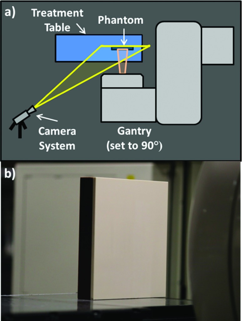
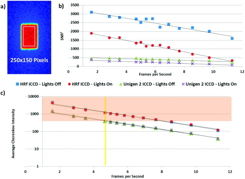
Methods: Complementary metal-oxide-semiconductor (CMOS), charge-coupled device (CCD), intensified charge-coupled device (ICCD), and electron multiplying-intensified charge coupled device (EM-ICCD) cameras were investigated to determine Cherenkov imaging performance in a clinical radiotherapy setting, with one emphasis on the maximum supportable frame rate. Where possible, the image intensifier was synchronized using a pulse signal from the Linac in order to image with room lighting conditions comparable to patient treatment scenarios. A solid water phantom irradiated with a 6 MV photon beam was imaged by the cameras to evaluate the maximum frame rate for adequate Cherenkov detection. Adequate detection was defined as an average electron count in the background-subtracted Cherenkov image region of interest in excess of 0.5% (327 counts) of the 16-bit maximum electron count value. Additionally, an ICCD and an EM-ICCD were each used clinically to image two patients undergoing whole-breast radiotherapy to compare clinical advantages and limitations of each system.
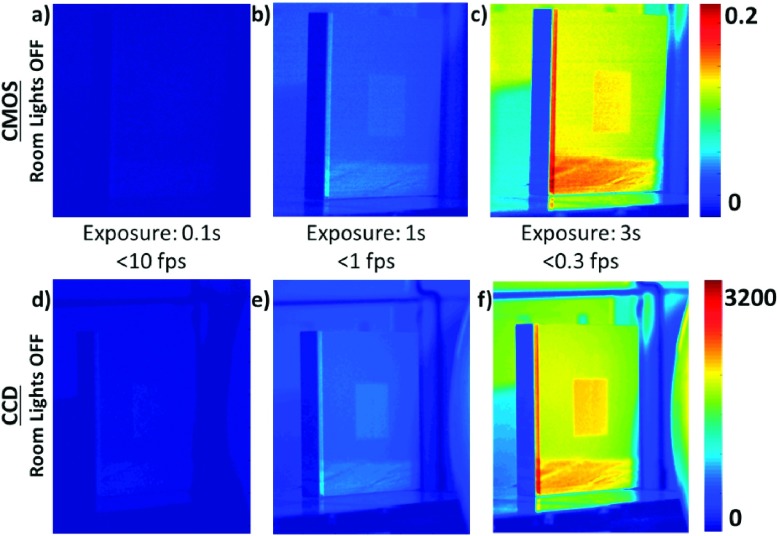
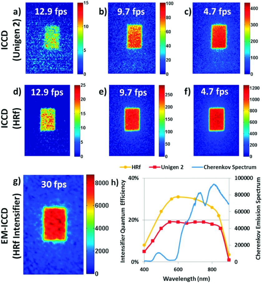
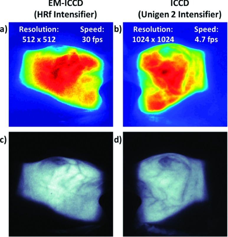
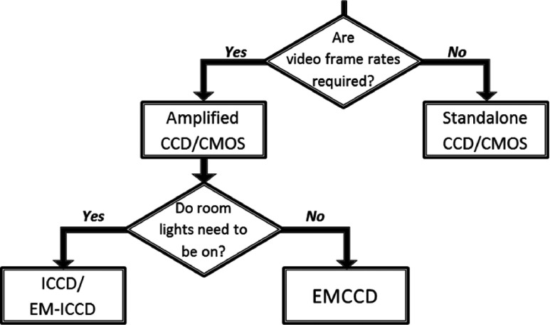
Results: Intensifier-coupled cameras were required for imaging Cherenkov emission on the phantom surface with ambient room lighting; standalone CMOS and CCD cameras were not viable. The EM-ICCD was able to collect images from a single Linac pulse delivering less than 0.05 cGy of dose at 30 frames/s (fps) and pixel resolution of 512 × 512, compared to an ICCD which was limited to 4.7 fps at 1024 × 1024 resolution. An intensifier with higher quantum efficiency at the entrance photocathode in the red wavelengths [30% quantum efficiency (QE) vs previous 19%] promises at least 8.6 fps at a resolution of 1024 × 1024 and lower monetary cost than the EM-ICCD.
Conclusions: The ICCD with an intensifier better optimized for red wavelengths was found to provide the best potential for real-time display (at least 8.6 fps) of radiation dose on the skin during treatment at a resolution of 1024 × 1024.
Figures
Similar articles
-
Cherenkov imaging method for rapid optimization of clinical treatment geometry in total skin electron beam therapy.Med Phys. 2016 Feb;43(2):993-1002. doi: 10.1118/1.4939880. Med Phys. 2016. PMID: 26843259 Free PMC article.
-
Remote Cherenkov imaging-based quality assurance of a magnetic resonance image-guided radiotherapy system.Med Phys. 2018 Jun;45(6):2647-2659. doi: 10.1002/mp.12919. Epub 2018 May 3. Med Phys. 2018. PMID: 29663429
-
An investigation of clinical treatment field delivery verification using cherenkov imaging: IMRT positioning shifts and field matching.Med Phys. 2019 Jan;46(1):302-317. doi: 10.1002/mp.13250. Epub 2018 Nov 19. Med Phys. 2019. PMID: 30346639
-
Camera technologies for low light imaging: overview and relative advantages.Methods Cell Biol. 2013;114:243-83. doi: 10.1016/B978-0-12-407761-4.00011-7. Methods Cell Biol. 2013. PMID: 23931510 Review.
-
One Year of Clinic-Wide Cherenkov Imaging for Discovery of Quality Improvement Opportunities in Radiation Therapy.Pract Radiat Oncol. 2023 Jan-Feb;13(1):71-81. doi: 10.1016/j.prro.2022.06.009. Epub 2022 Jun 29. Pract Radiat Oncol. 2023. PMID: 35777728 Free PMC article. Review.
Cited by
-
Cherenkov emissions for studying tumor changes during radiation therapy: An exploratory study in domesticated dogs with naturally-occurring cancer.PLoS One. 2020 Aug 26;15(8):e0238106. doi: 10.1371/journal.pone.0238106. eCollection 2020. PLoS One. 2020. PMID: 32845905 Free PMC article.
-
Cherenkov Imaged Bio-Morphological Features Verify Patient Positioning With Deformable Tissue Translocation in Breast Radiation Therapy.ArXiv [Preprint]. 2025 Aug 19:arXiv:2409.05680v2. ArXiv. 2025. Update in: Adv Radiat Oncol. 2024 Nov 19;10(4):101684. doi: 10.1016/j.adro.2024.101684. PMID: 40895086 Free PMC article. Updated. Preprint.
-
Cherenkov imaging method for rapid optimization of clinical treatment geometry in total skin electron beam therapy.Med Phys. 2016 Feb;43(2):993-1002. doi: 10.1118/1.4939880. Med Phys. 2016. PMID: 26843259 Free PMC article.
-
Advances and potential of optical surface imaging in radiotherapy.Phys Med Biol. 2022 Aug 9;67(16):10.1088/1361-6560/ac838f. doi: 10.1088/1361-6560/ac838f. Phys Med Biol. 2022. PMID: 35868290 Free PMC article. Review.
-
Cherenkov imaging for linac beam shape analysis as a remote electronic quality assessment verification tool.Med Phys. 2019 Feb;46(2):811-821. doi: 10.1002/mp.13303. Epub 2018 Dec 14. Med Phys. 2019. PMID: 30471126 Free PMC article.
References
-
- Bloemen-van Gurp E. J., Mijnheer B. J., Verschueren T. A. M., and Lambin P., “Total body irradiation, toward optimal individual delivery: Dose evaluation with metal oxide field effect transistors, thermoluminescence detectors, and a treatment planning system,” Int. J. Radiat. Oncol., Biol., Phys. 69(4), 1297–1304 (2007).10.1016/j.ijrobp.2007.07.2334 - DOI - PubMed
Publication types
MeSH terms
Grants and funding
LinkOut - more resources
Full Text Sources
Other Literature Sources
Miscellaneous
