

Numerical implementation of multiple peeling theory and its application to spider web anchorages
- PMID: 25657835
- PMCID: PMC4275870
- DOI: 10.1098/rsfs.2014.0051
Numerical implementation of multiple peeling theory and its application to spider web anchorages
Abstract
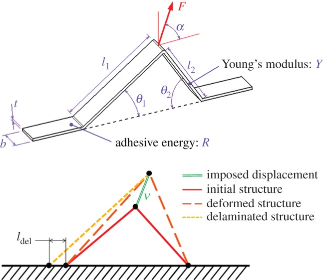
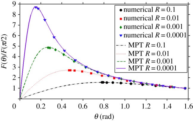
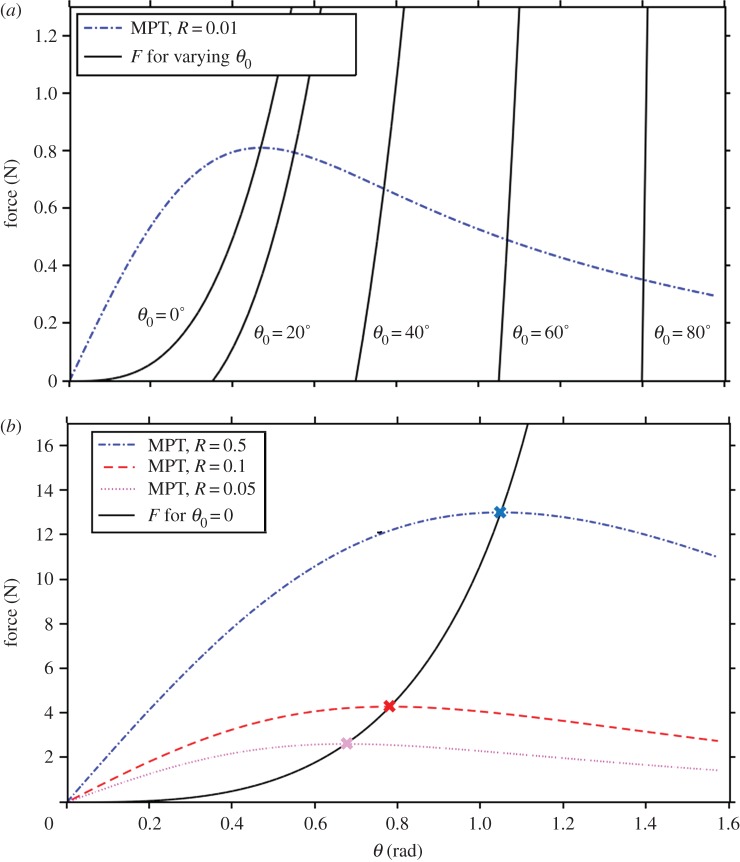
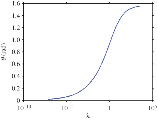
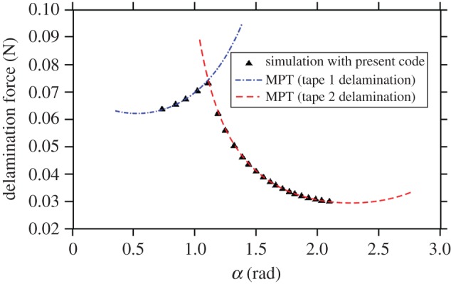
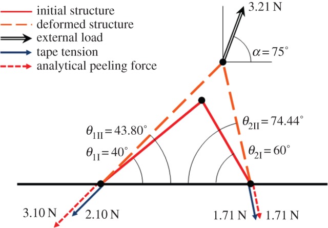
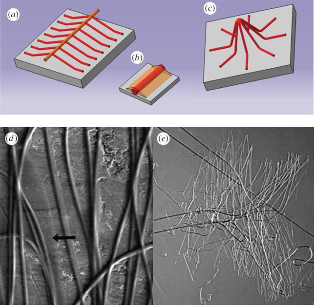
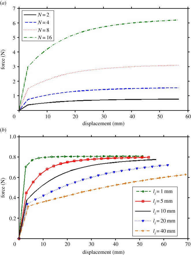
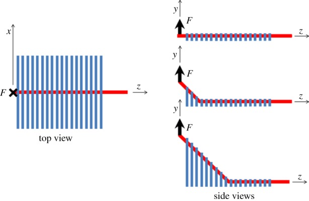
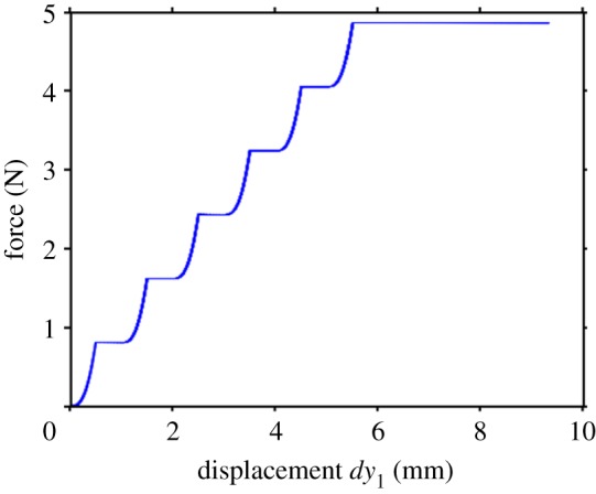
Adhesion of spider web anchorages has been studied in recent years, including the specific functionalities achieved through different architectures. To better understand the delamination mechanisms of these and other biological or artificial fibrillar adhesives, and how their adhesion can be optimized, we develop a novel numerical model to simulate the multiple peeling of structures with arbitrary branching and adhesion angles, including complex architectures. The numerical model is based on a recently developed multiple peeling theory, which extends the energy-based single peeling theory of Kendall, and can be applied to arbitrarily complex structures. In particular, we numerically show that a multiple peeling problem can be treated as the superposition of single peeling configurations even for complex structures. Finally, we apply the developed numerical approach to study spider web anchorages, showing how their function is achieved through optimal geometrical configurations.
Keywords: adhesion; multiple peeling; numerical simulations; spider web anchorages.
Figures
Similar articles
-
Competition between delamination and tearing in multiple peeling problems.J R Soc Interface. 2019 Nov 29;16(160):20190388. doi: 10.1098/rsif.2019.0388. Epub 2019 Nov 27. J R Soc Interface. 2019. PMID: 31771420 Free PMC article.
-
Three-dimensional printing spiders: back-and-forth glue application yields silk anchorages with high pull-off resistance under varying loading situations.J R Soc Interface. 2017 Feb;14(127):20160783. doi: 10.1098/rsif.2016.0783. J R Soc Interface. 2017. PMID: 28228539 Free PMC article.
-
Synergetic material and structure optimization yields robust spider web anchorages.Small. 2013 Aug 26;9(16):2747-56. doi: 10.1002/smll.201201343. Epub 2013 Apr 15. Small. 2013. PMID: 23585296
-
Recent advances in chemical peeling in Japan.J Dermatol. 2006 Oct;33(10):655-61. doi: 10.1111/j.1346-8138.2006.00155.x. J Dermatol. 2006. PMID: 17040493 Review.
-
Potential and constraints for the application of CFD combined with Lagrangian particle tracking to dry powder inhalers.Eur J Pharm Sci. 2019 Feb 1;128:299-324. doi: 10.1016/j.ejps.2018.12.008. Epub 2018 Dec 14. Eur J Pharm Sci. 2019. PMID: 30553814 Review.
Cited by
-
Competition between delamination and tearing in multiple peeling problems.J R Soc Interface. 2019 Nov 29;16(160):20190388. doi: 10.1098/rsif.2019.0388. Epub 2019 Nov 27. J R Soc Interface. 2019. PMID: 31771420 Free PMC article.
-
Imaging and mechanical characterization of different junctions in spider orb webs.Sci Rep. 2019 Apr 8;9(1):5776. doi: 10.1038/s41598-019-42070-8. Sci Rep. 2019. PMID: 30962468 Free PMC article.
-
The role of adhesion in contact mechanics.J R Soc Interface. 2019 Feb 28;16(151):20180738. doi: 10.1098/rsif.2018.0738. J R Soc Interface. 2019. PMID: 30958203 Free PMC article.
-
Three-dimensional printing spiders: back-and-forth glue application yields silk anchorages with high pull-off resistance under varying loading situations.J R Soc Interface. 2017 Feb;14(127):20160783. doi: 10.1098/rsif.2016.0783. J R Soc Interface. 2017. PMID: 28228539 Free PMC article.
-
Attachment discs of the diving bell spider Argyroneta aquatica.Commun Biol. 2023 Dec 6;6(1):1232. doi: 10.1038/s42003-023-05575-7. Commun Biol. 2023. PMID: 38057422 Free PMC article.
References
-
- Smith AM, Callow JA. 2006. Biological adhesives. Berlin, Germany: Springer.
-
- Yao H, Gao H. 2006. Mechanics of robust and releasable adhesion in biology: bottom–up designed hierarchical structures of gecko. J. Mech. Phys. Solids 54, 1120–1146. (10.1016/j.jmps.2006.01.002) - DOI
-
- Sahni V, Blackledge TA, Dhinojwala A. 2011. A review on spider silk adhesion. J. Adhesion 87, 595–614. (10.1080/00218464.2011.583588) - DOI
LinkOut - more resources
Full Text Sources
Other Literature Sources
