

Three-axis MR-conditional robot for high-intensity focused ultrasound for treating prostate diseases transrectally
- PMID: 25657846
- PMCID: PMC4318438
- DOI: 10.1186/s40349-014-0023-2
Three-axis MR-conditional robot for high-intensity focused ultrasound for treating prostate diseases transrectally
Abstract
Background: A prototype magnetic resonance image (MRI)-conditional robot was developed for navigating a high-intensity focused ultrasound (HIFU) system in order to treat prostate cancer transrectally.
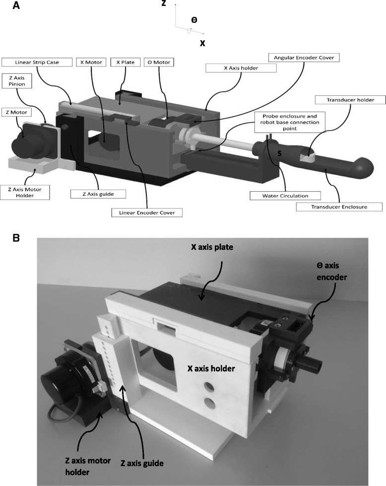
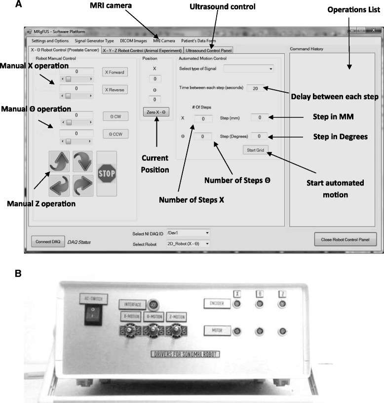
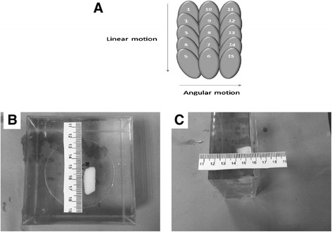
Materials and methods: The developed robotic device utilizes three PC-controlled axes: a linear axis for motion along the rectum, an angular axis for rotation in the rectum, and a linear axis to lift the robot up and down. Experiments with the system were performed in a 1.5-T MRI system using gel phantoms.
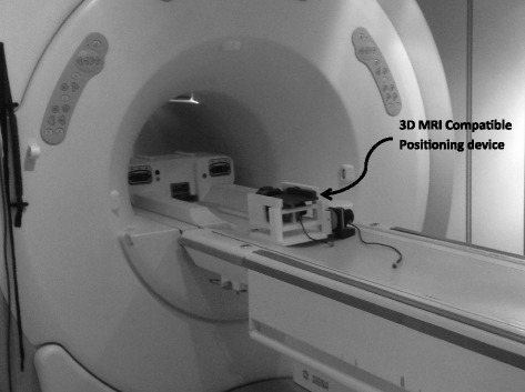
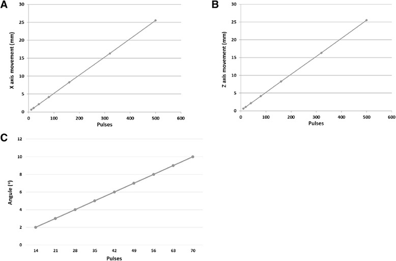
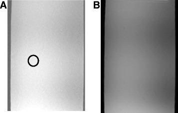
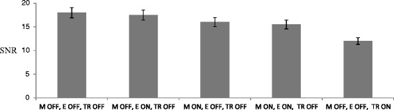
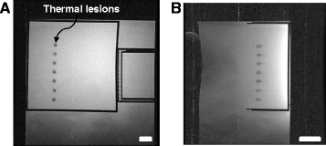
Result: The robot was successfully operated in a 1.5-T clinical MRI system. The effect of piezoelectric motors and optical encoders was quantified based on the reduction of signal to noise ratio. Discrete and overlapping lesions were created accurately by moving the HIFU transducer with the robotic device.
Conclusion: An MRI-conditional HIFU robot was developed which can create controlled thermal lesions under MRI guidance. The intention is to use this robot transrectally in the future for the treatment of prostate cancer.
Figures
Similar articles
-
MRI-compatible positioning device for guiding a focused ultrasound system for transrectal treatment of prostate cancer.Int J Comput Assist Radiol Surg. 2014 Jul;9(4):745-53. doi: 10.1007/s11548-013-0964-x. Epub 2013 Dec 13. Int J Comput Assist Radiol Surg. 2014. PMID: 24337790
-
MRI guided focused ultrasound robotic system for the treatment of gynaecological tumors.Int J Med Robot. 2016 Mar;12(1):46-52. doi: 10.1002/rcs.1653. Epub 2015 Mar 25. Int J Med Robot. 2016. PMID: 25808561
-
MRI-guided focused ultrasound robotic system for the treatment of bone cancer.Int J Med Robot. 2017 Mar;13(1). doi: 10.1002/rcs.1753. Epub 2016 Jul 15. Int J Med Robot. 2017. PMID: 27422861
-
Magnetic Resonance-Guided High-Intensity Focused Ultrasound (MR-HIFU): Technical Background and Overview of Current Clinical Applications (Part 1).Rofo. 2019 Jun;191(6):522-530. doi: 10.1055/a-0817-5645. Epub 2019 Jan 10. Rofo. 2019. PMID: 30630200 Review. English.
-
Magnetic Resonance-Guided High-Intensity Focused Ultrasound (MR-HIFU): Overview of Emerging Applications (Part 2).Rofo. 2019 Jun;191(6):531-539. doi: 10.1055/a-0817-5686. Epub 2019 Jan 10. Rofo. 2019. PMID: 30630199 Review. English.
Cited by
-
Magnetic Resonance Imaging-Guided Focused Ultrasound Positioning System for Preclinical Studies in Small Animals.J Ultrasound Med. 2021 Jul;40(7):1343-1352. doi: 10.1002/jum.15514. Epub 2020 Oct 8. J Ultrasound Med. 2021. PMID: 33031567 Free PMC article.
-
Treatment of canine and feline sarcoma using MR-guided focused ultrasound system.J Ultrasound. 2022 Dec;25(4):895-904. doi: 10.1007/s40477-022-00672-5. Epub 2022 Mar 12. J Ultrasound. 2022. PMID: 35277843 Free PMC article.
-
Review of Robot-Assisted HIFU Therapy.Sensors (Basel). 2023 Apr 3;23(7):3707. doi: 10.3390/s23073707. Sensors (Basel). 2023. PMID: 37050766 Free PMC article. Review.
-
Simple methods to test the accuracy of MRgFUS robotic systems.Int J Med Robot. 2021 Aug;17(4):e2287. doi: 10.1002/rcs.2287. Epub 2021 May 31. Int J Med Robot. 2021. PMID: 34021694 Free PMC article.
-
An Out-of-Plane Operated Soft Engine Driving Stretchable Zone Plate for Adjusting Focal Point of an Ultrasonic Beam.Sensors (Basel). 2019 Sep 4;19(18):3819. doi: 10.3390/s19183819. Sensors (Basel). 2019. PMID: 31487858 Free PMC article.
References
-
- Cline H, Rohling K, Abeling W. Mechanical positioner for magnetic resonance guided ultrasound therapy. United States patent US: Inventors General Electric Company, assignee; 1995. p. 5443068.
-
- Yehezkeli O, Freundlich D, Magen N, Marantz C, Medan Y, Vitek S, Weinreb A. Mechanical positioner for MRI guided ultrasound therapy system. Inventors word intellectual property organization, INSIGHTEC-TXSONICSLTD, assignee, WO0209812. 2002.
LinkOut - more resources
Full Text Sources
Other Literature Sources
