. 2015 Mar 11;15(3):1867-75.
doi: 10.1021/nl5046632. Epub 2015 Feb 17.

Nucleation control for large, single crystalline domains of monolayer hexagonal boron nitride via Si-doped Fe catalysts

Affiliations

Nucleation control for large, single crystalline domains of monolayer hexagonal boron nitride via Si-doped Fe catalysts

Sabina Caneva et al. Nano Lett. .

Abstract

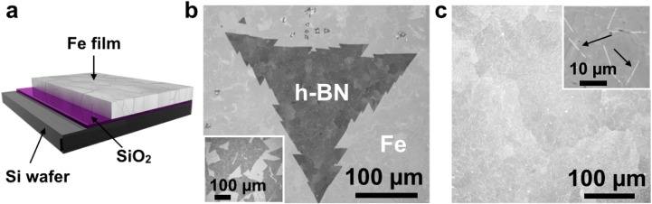
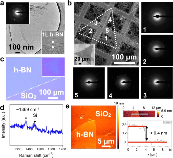
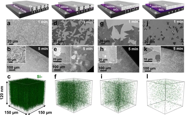
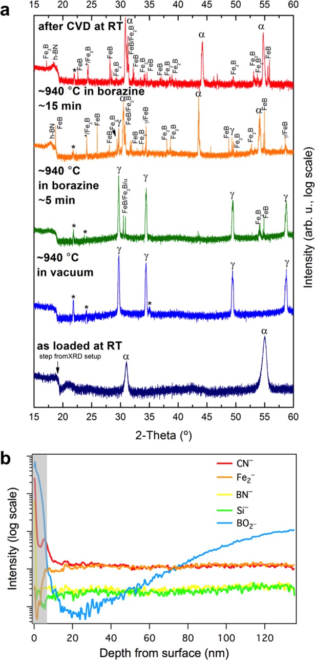
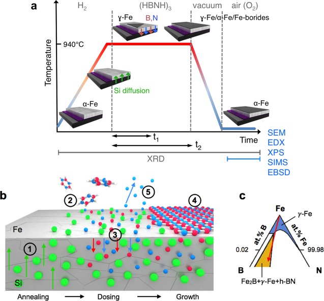
The scalable chemical vapor deposition of monolayer hexagonal boron nitride (h-BN) single crystals, with lateral dimensions of ∼0.3 mm, and of continuous h-BN monolayer films with large domain sizes (>25 μm) is demonstrated via an admixture of Si to Fe catalyst films. A simple thin-film Fe/SiO2/Si catalyst system is used to show that controlled Si diffusion into the Fe catalyst allows exclusive nucleation of monolayer h-BN with very low nucleation densities upon exposure to undiluted borazine. Our systematic in situ and ex situ characterization of this catalyst system establishes a basis for further rational catalyst design for compound 2D materials.

Keywords: Fe catalyst; Hexagonal boron nitride (h-BN); borazine (HBNH)3; chemical vapor deposition (CVD); in situ X-ray diffraction (XRD); secondary ion mass spectrometry (SIMS).


Figures

Figure 1
Figure 1
(a) Schematic of catalyst system composed of Fe/SiO2/Si. (b) SEM image of a large, tooth-edged h-BN domain grown at 940 °C and 1 × 10⁻³ mbar borazine exposure for 5 min (standard conditions) on Fe(1000 nm)/SiO2(300 nm)/Si substrates. Inset: corresponding low magnification SEM image. (c) Continuous h-BN film homogeneously covering the Fe surface after 5 min of higher pressure borazine exposure (6 × 10⁻³ mbar) at 940 °C. The individual domain boundaries can be easily identified, as indicated by the black arrows (top right inset).
Figure 2
Figure 2
(a) Low-resolution TEM image of a suspended h-BN film (CVD conditions and substrate as in Figure 1b) supported on holey carbon, copper mesh TEM grid, with corresponding hexagonal electron diffraction pattern (top left inset) and edge analysis, confirming the single layer nature of the film (bottom right inset). (b) SAED study on a large triangular h-BN domain (standard CVD conditions). The SEM image shows the location of the domain (enclosed by the white dotted lines). The inset shows a similar triangle as-grown on the catalyst before transfer. The five diffraction patterns obtained from well-spaced regions of the domain have identical orientation, thus confirming it is a single crystal. (c) Optical image of a continuous h-BN film transferred onto a SiO2(300 nm)/Si wafer via the electrochemical bubbling method. The inset shows a transferred triangular domain from the sample in Figure 1b. (d) Raman spectrum measured at the center of one of the triangular domains in c, showing the characteristic h-BN signal at 1369 cm–1. The additional peak at ∼1450 cm–1 can be attributed to third-order scattering from Si. (e) AFM topography image of the tip of a h-BN triangle with detail of a domain edge (right) and corresponding step-height measurement taken at the position of the white line.
Figure 3
Figure 3
Schematics of the catalyst system and SEM images of the surface after growth at 940 °C and 3 × 10⁻³ mbar borazine exposure for 1 min (a,d,g,j) and 5 min (b,e,h,k) for Fe/SiO2(x)/Si substrates, where x = native, 200, 500, and 2000 nm, respectively. SIMS 3D maps (c,f,i,l) showing the Si distributions in top 120 nm of the surface, corresponding to the samples respectively shown in (a,d,g,j).
Figure 4
Figure 4
(a) Surface sensitive in situ XRD patterns of a Fe/SiO2(300 nm)/Si sample during the salient stages of the CVD process. Fe undergoes a thermally induced phase transformation from as-deposited α-Fe to γ-Fe upon heating to 940 °C. Vacuum annealing at 940 °C leads to the appearance of reflections that can be ascribed to iron silicates, Fe2SiO4 (labeled with “*”). Upon borazine exposure (1 × 10⁻³ mbar) isothermal h-BN growth is indicated by the appearance of a reflection at ∼18°. For short (5 min) borazine exposure the catalyst phase stays predominantly γ-Fe, while for extended (15 min) borazine feeding the appearance of Fe-boride phases (FeB and Fe2B) indicates B dissolution into Fe, and an isothermal transformation of γ-Fe to α-Fe is observed (possibly linked to further B and/or Si diffusion, see Figure S9). The room temperature phase after CVD is almost fully α-Fe. We note that intensity is plotted here on a log scale to emphasize minority phases. Figure S7 shows the same data plotted on a linear scale. (b) SIMS depth distribution of the top 120 nm from the surface of B, N, Si, and Fe related species of a Fe/SiO2(500 nm)/Si sample, indicating a number of distinct regions of material distribution, showing a nitrogen rich surface layer followed by an oxygen rich region over the next ∼6 nm (shaded area). The h-BN was grown for 5 min at 940 °C and 3 × 10⁻³ mbar.
Figure 5
Figure 5
(a) Schematic illustrating the salient stages of the CVD process for the conditions used in this work. The 3D diagrams depict the state of the catalyst system during these steps, and the green, red, and blue arrows indicate the incorporation of Si, B and N into the Fe bulk, respectively. We note that the Fe undergoes a phase transformation during annealing, which reverts either upon cooling after short borazine exposure times (t1) or isothermally at temperature for longer borazine exposure times (t2). The gray labels on the bottom of the schematic indicate at which stages the various characterization techniques were performed. (b) Schematic of the growth model for h-BN CVD on Fe/SiO2/Si substrates: (1) Annealing: onset of Si diffusion into the catalyst; (2) exposure: the borazine molecules impinge on the surface where they dehydrogenate and dissociate; (3) B and N species diffuse into the Fe catalyst; (4) nucleation and growth of h-BN; (5) possible desorption of surface N to gas phase. (c) detail of the Fe-rich corner of the Fe–B–N ternary phase diagram in the isothermal section at 950 °C. The blue region corresponds to the solid solution of B and N in γ-Fe. The yellow region corresponds the three-phase equilibrium of Fe2B, γ-Fe, and h-BN. The red arrow indicates the suggested reaction pathway during CVD of h-BN on Fe films.

References

    1. Novoselov K. S.; Fal’ko V. I.; Colombo L.; Gellert P. R.; Schwab M. G.; Kim K. Nature 2012, 490, 192–200. - PubMed
    1. Butler S. Z.; Hollen S. M.; Cao L.; Cui Y.; Gupta J. A.; Gutie H. R.; Heinz T. F.; Hong S. S.; Huang J.; Ismach A. F.; Johnston-Halperin E.; Kuno M.; Plashnitsa V. V.; Robinson R. D.; Ruoff R. S.; Salahuddin S.; Shan J.; Shi L.; Spencer O. M. G.; Terrones M.; Windl W.; Goldberger J. E. ACS Nano 2013, 7, 2898–2926. - PubMed
    1. Fiori G.; Bonaccorso F.; Iannaccone G.; Palacios T.; Neumaier D.; Seabaugh A.; Banerjee S. K.; Colombo L. Nat. Nanotechnol. 2014, 9, 768–779. - PubMed
    1. Focus Issue in Nat. Nanotechnol. 2014, 9, 725–807. - PubMed
    1. Weatherup R. S.; Amara H.; Blume R.; Dlubak B.; Bayer B. C.; Diarra M.; Bahri M.; Cabrero-Vilatela A.; Caneva S.; Kidambi P. R.; Martin M.-B.; Deranlot C.; Seneor P.; Schloegl R.; Ducastelle F.; Bichara C.; Hofmann S. J. Am. Chem. Soc. 2014, 136, 13698–13708. - PMC - PubMed

Publication types

LinkOut - more resources