Case Reports
. 2015 Jan 29:7:25-31.
doi: 10.2147/CCIDE.S76637. eCollection 2015.

Progressive immediate loading of a perforated maxillary sinus dental implant: a case report

Affiliations
Case Reports

Progressive immediate loading of a perforated maxillary sinus dental implant: a case report

Mohammed Jasim Al-Juboori. Clin Cosmet Investig Dent. .

Abstract

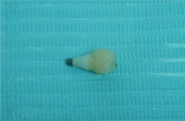
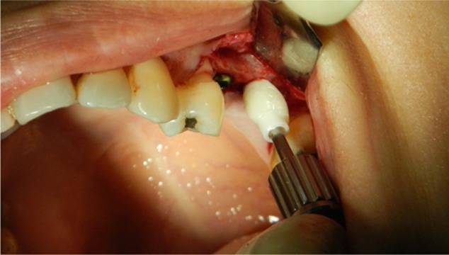
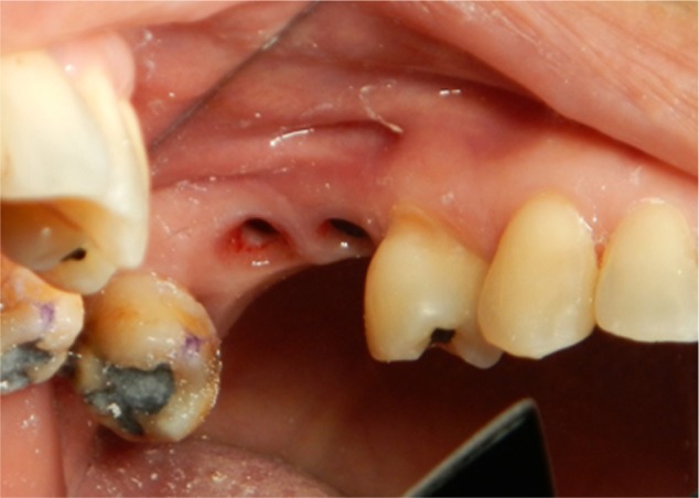
The displacement of a dental implant into the maxillary sinus may lead to implant failure due to exposure of the apical third or the tip of the implant beyond the bone, resulting in soft tissue growth. This case report discusses dental implant placement in the upper first molar area with maxillary sinus involvement of approximately 2 mm. A new technique for progressive implant loading was used, involving immediately loaded implants with maxillary sinus perforation and low primary stability. Follow-up was performed with resonance frequency analysis and compared with an implant placed adjacent in the upper second premolar area using a conventional delayed loading protocol. Implants with maxillary sinus involvement showed increasing stability during the healing period. We found that progressive implant loading may be a safe technique for the placement of immediately loaded implants with maxillary sinus involvement.

Keywords: bone density; implant stability; maxillary sinus; progressive implant loading; provisional crown; resonance frequency analysis.


Figures

Figure 1
Figure 1
Orthopantamograph taken preoperatively showing maxillary sinus pneumatization in the extracted site 25 and 26 area.
Figure 2
Figure 2
Temporary abutment with crown fabrication from composite filling for easy adjustment and modification. Fabrication, contouring, and polishing were performed outside the patient’s mouth.
Figure 3
Figure 3
Temporary abutment and crown installed into the 26-position implant and torque before flap closure. Cover screw used for the 25-position implant, which was placed with the submerged technique and left to heal for 2 months before re-entry.
Figure 4
Figure 4
Occlusion was checked before releasing the patient. The crown was left out of occlusion to prevent any occlusal loading during the early healing period.
Figure 5
Figure 5
Occlusal view of the temporary abutment and crown issued on the day of surgery (implant placement); small occlusal table with no adjacent tooth contact. The flap was adapted around the crown (simultaneously covering the 25-position implant) and sutured with nylon sutures.
Figure 6
Figure 6
An immediate postoperative periapical radiograph showing the 16-position implant penetrating the maxillary sinus by a few millimeters.
Figure 7
Figure 7
Second stage of temporary crown modification 1 month after implant placement. The crown now has contact with adjacent tooth 27, as it has a wider diameter but is still out of occlusion.
Figure 8
Figure 8
Third stage of temporary crown modification. After 2 months of implant placement, an increase in the diameter of the crown was done. The crown was contoured to resemble the natural tooth anatomy.
Figure 9
Figure 9
Temporary crown increased in size, and implant with light center occlusion. The implant in position 25 is now exposed, and the healing abutment is installed.
Figure 10
Figure 10
Differences are seen in the gingival contour around temporary crown 26 and healing abutment in the 25-position implant. The emergence profile is achieved, and interdental papillae are growing around the temporary abutment.
Figure 11
Figure 11
Acrylic provisional crown received from the laboratory and issued with a customized abutment; only light and centric occlusion is allowed on the provisional crowns.
Figure 12
Figure 12
Periapical radiograph after abutment installation does not reveal any bone resorption or radiolucencies around either implant, with a stable bone crest around the 26-position implant despite many abutment disconnections. There are no complications in the apical penetrating part of the 26-position implant.

References

    1. Lekholm U, Zarb G. Patient selection and preparation. In: Bffmemark P-I, Zarb G, Albrektsson T, editors. Tissue-Integrated Prosthesis: Osseointegration in Clinical Dentistry. Chicago, IL, USA: Quintessence; 1985.
    1. Bischof M, Nedir R, Szmukler-Moncler S, Bernard JP, Samson J. Implant stability measurement of delayed and immediately loaded implants during healing. Clin Oral Implants Res. 2004;15:529–539. - PubMed
    1. Mesa F, Munoz R, Noguerol B, de Dios Luna J, Galindo P, O’Valle F. Multivariate study of factors influencing primary dental implant stability. Clin Oral Implants Res. 2008;19:196–200. - PubMed
    1. Lorenzoni M, Pertl C, Zhang K, Wegscheider WA. Inpatient comparison of immediately loaded and nonleaded implants within 6 months. Clin Oral Implants Res. 2003;14:273–279. - PubMed
    1. Jaffin RA, Berman CL. The excessive loss of Branemark fixtures in type IV bone: a 5-year analysis. J Periodontol. 1991;62:2–4. - PubMed

Publication types

LinkOut - more resources