. 2015 Oct;22(10):1665-75.
doi: 10.1038/cdd.2015.15. Epub 2015 Mar 6.

Bak apoptotic pores involve a flexible C-terminal region and juxtaposition of the C-terminal transmembrane domains

Affiliations

Bak apoptotic pores involve a flexible C-terminal region and juxtaposition of the C-terminal transmembrane domains

S Iyer et al. Cell Death Differ. 2015 Oct.

Abstract

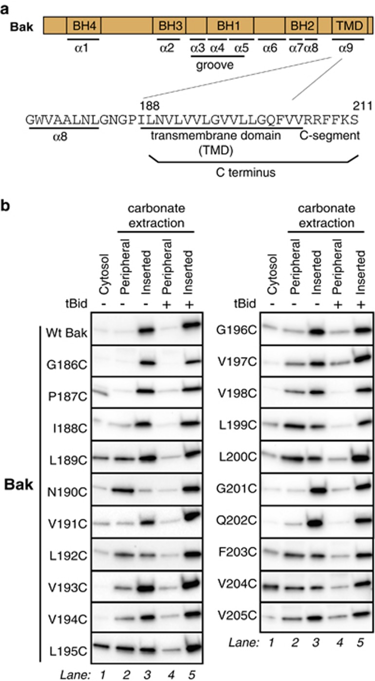
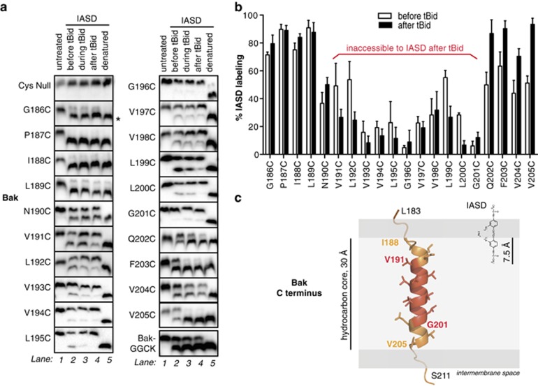
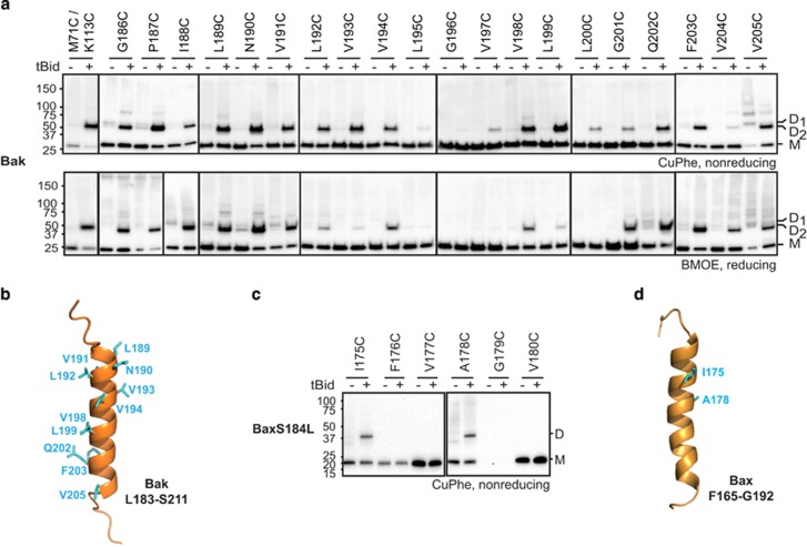
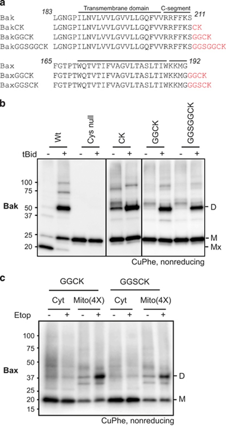
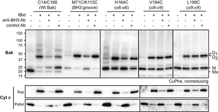
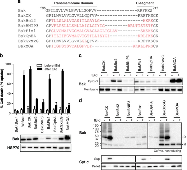
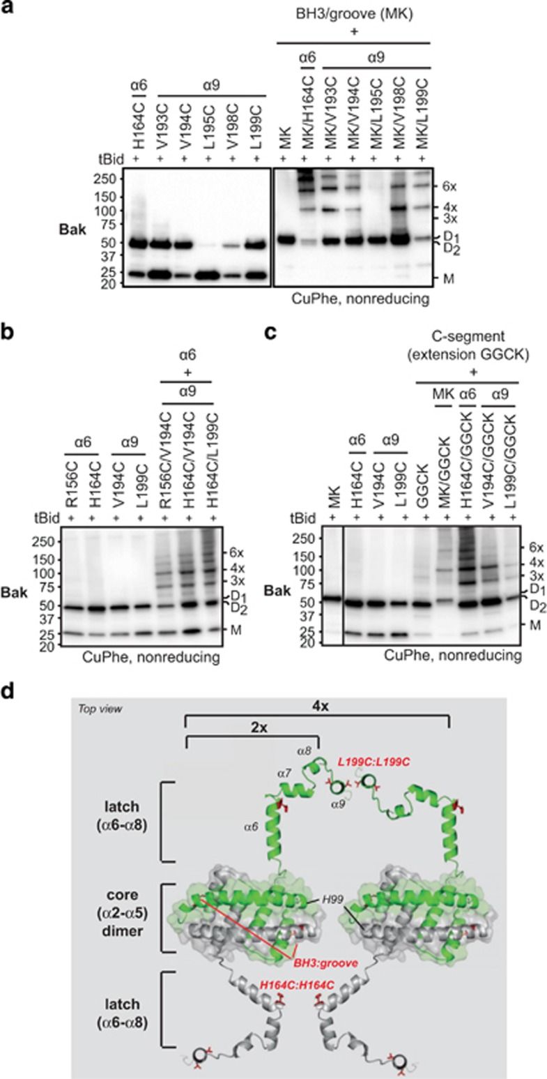
Bak and Bax mediate apoptotic cell death by oligomerizing and forming a pore in the mitochondrial outer membrane. Both proteins anchor to the outer membrane via a C-terminal transmembrane domain, although its topology within the apoptotic pore is not known. Cysteine-scanning mutagenesis and hydrophilic labeling confirmed that in healthy mitochondria the Bak α9 segment traverses the outer membrane, with 11 central residues shielded from labeling. After pore formation those residues remained shielded, indicating that α9 does not line a pore. Bak (and Bax) activation allowed linkage of α9 to neighboring α9 segments, identifying an α9:α9 interface in Bak (and Bax) oligomers. Although the linkage pattern along α9 indicated a preferred packing surface, there was no evidence of a dimerization motif. Rather, the interface was invoked in part by Bak conformation change and in part by BH3:groove dimerization. The α9:α9 interaction may constitute a secondary interface in Bak oligomers, as it could link BH3:groove dimers to high-order oligomers. Moreover, as high-order oligomers were generated when α9:α9 linkage in the membrane was combined with α6:α6 linkage on the membrane surface, the α6-α9 region in oligomerized Bak is flexible. These findings provide the first view of Bak carboxy terminus (C terminus) membrane topology within the apoptotic pore.


Figures

Figure 1
Figure 1
Cysteine substitutions in α9 can hinder Bak mitochondrial insertion, but only prior to apoptosis. (a) The Bak C terminus comprises a hydrophobic transmembrane domain and a basic C-segment. Positions of the four Bcl-2 homology (BH) domains and C-terminal transmembrane domain in Bak are shown, as is part of the human Bak sequence. (b) Bak mitochondrial localization is decreased by cysteine substitutions in α9, but membrane insertion is complete after activation by tBid. Untreated cells were fractionated into cytosol and membrane fractions, and the membrane fractions then extracted with sodium carbonate to detect peripherally attached and membrane-inserted populations. Where indicated, membrane fractions were pre-treated with tBid to activate Bak. Data are representative of three independent experiments
Figure 2
Figure 2
Bak α9 traverses the MOM but does not line a pore following apoptosis. (a) Cysteine accessibility approach reveals the transmembrane nature of Bak α9. Membrane fractions from MEFs expressing the indicated Bak variants were incubated with tBid and IASD as follows. In lane 1, mitochondria-enriched membranes were untreated. In lanes 2 and 4, membranes were incubated in the absence or presence of tBid, and then with IASD. In lane 3, IASD was present during the tBid incubation to detect both transient and persistent exposure. In lane 5, membranes were solubilized with detergent prior to treatment with IASD to obtain complete labeling. Samples were run on one-dimensional isoelectric focusing gels and immunoblotted for Bak. Asterisk (*) denotes IASD-labeled Bak. BakGGCK has four residues (GGCK) added to the carboxy terminus (see Figure 4). Data are representative of three independent experiments. (b) Quantified IASD labeling of Bak α9 before and after tBid. Data are mean±S.D. of three independent experiments. (c) Membrane topology of the Bak C terminus prior to Bak activation. As the Bak C terminus is not present in the X-ray structure of Bak, the Jpred-3 structure prediction server was used to predict which residues are likely to adopt an α-helical geometry (I188–V205). The structure of α9 was modeled using the SyByL software. The α-helix was then positioned in the membrane assuming that IASD is able to label cysteine side-chains 7.5 Å into the hydrocarbon core due to the distance between the charged (hydrophilic) and reactive (iodoacetamide) groups of IASD. Assuming 1.5 Å per residue for the α-helical conformation, the 11 IASD-inaccessible residues (red) can span 15 Å in the center of the hydrocarbon bilayer. We cannot rule out that α9 adopts a 310-helix configuration; in this case, the TMD would extend ~3 Å longer than an α-helix, changing the side-chain orientation on the α9 carboxy terminus, potentially beyond the confines of the membrane. The width of the hydrocarbon bilayer is represented as 30 Å
Figure 3
Figure 3
The Bak and Bax α9 helices can be linked following an apoptotic stimulus. (a) Intermolecular α9:α9 linkage can be captured after Bak becomes activated. Membrane fractions from Bak−/−Bax−/− MEFs expressing the indicated Bak cysteine variants were incubated without or with tBid prior to treatment with the oxidant CuPhe (upper panel) or the crosslinker BMOE (lower panel). Unlinked Bak (M, monomer) or linked Bak (D, dimer) was detected following SDS-PAGE (nonreducing for CuPhe) and immunoblotting for Bak. To compare with linkage at the BH3:groove interface, the M71C/K113C variant is included in lanes 1 and 2. (The BH3:groove-linked dimers (D1) migrate slower than dimers linked at the α9:α9 interface (D2), and the M71C/K113C samples were run on the same gels as the L189C, N190C and V191C samples.) Data are representative of at least three independent experiments. (b) Linkage pattern at the α9:α9 interface in activated Bak. Cartoon of the Bak C terminus from Figure 2c highlighting residues (cyan) that can link to the equivalent residue in a neighboring activated Bak molecule. (c) Intermolecular α9:α9 linkage can be captured after BaxS184L becomes activated. Membrane fractions from Bak−/−Bax−/− MEFs expressing the indicated BaxS184L cysteine variants were incubated with tBid and CuPhe as in a. Data are representative of at least three independent experiments. (d) Linkage pattern at the α9:α9 interface in activated BaxS184L. Cartoon of the Bax C terminus (1F16) highlighting residues (cyan) that can link to the equivalent residue in a neighboring activated BaxS184L molecule
Figure 4
Figure 4
Extensions to the C-segments of Bak and Bax can be linked only after Bak and Bax are activated. (a) Extensions to the C-segments. Extra residues (red) added to Bak and Bax contain cysteine to monitor linkage, glycine to provide flexibility, and lysine to encourage targeting and insertion into the MOM. (b) C-segment extensions to Bak can be linked after but not before apoptosis. Membrane fractions from Bak−/−Bax−/− MEFs expressing the indicated C-segment variants were incubated without or with tBid prior to treatment with CuPhe. Samples were analyzed as in Figure 3a. Mx indicates an intramolecular cysteine disulfide bond (C14:C166) in nonactivated wt Bak. Note that in the absence of tBid, some linkage to other mitochondrial proteins was evident (Figure 4b), as observed for the nearby V205C (Figure 3a). Note also that some degree of linkage routinely occurred in the CK variant, suggesting that this variant may be arranged a little differently to other variants prior to its activation. Data are representative of at least three independent experiments. (c) C-segment extensions to Bax can be linked after but not before apoptosis. Bak−/−Bax−/− MEFs expressing the indicated C-segment variants were cultured in the presence of etoposide, and the cytosol (Cyt) and membrane (Mito) fractions incubated with CuPhe. The cytosol and fourfold-enriched membrane fractions were analyzed as in Figure 3a, but immunoblotted for Bax. Data are representative of at least three independent experiments
Figure 5
Figure 5
The Bak α9:α9 interface is not impeded when an antibody inhibits the BH3:groove interface. Membrane fractions from Bak−/−Bax−/− MEFs expressing the indicated cysteine variants were incubated without or with tBid. Where indicated, an anti-BH3 (4B5) or control antibody to the Bak N terminus (8F8) was also present (at 5 μg per 50 μl sample) during the incubation. Aliquots were assessed for cysteine linkage by CuPhe as in Figure 3a, or for cytochrome c release. Mx indicates an intramolecular cysteine disulfide bond (C14:C166) in nonactivated wt Bak. Data are representative of at least three independent experiments
Figure 6
Figure 6
An alternative C terminus in Bak can also be linked after oligomerization. (a) Sequences of Bak C-terminal chimeras. The whole C terminus (186-211) of Bak was replaced with that of Bcl-2, BNIP3, Fis1, glycophorin A (GpHA) or monoamine oxidase A (MOA) (highlighted in red). To generate a glycophorin-like dimerization motif (GxxxG) in Bak α9, two residues (LG) were reversed to obtain 196GVVLG201. Cysteine and lysine were added to monitor linkage and to encourage targeting and insertion into the MOM, as in Figure 4. (b) Bak containing the Fis1 C terminus retains stability and function. Bak−/−Bax−/− MEFs expressing the indicated Bak chimeras were treated with etoposide and assessed for cell death (top panel). Data are mean±S.D. from three independent experiments. Total cell lysates from untreated cells were immunoblotted for Bak, and for HSP70 as a loading control (bottom panels). (c) BakFis1 is semi-cytosolic but can translocate to mitochondria after tBid. Permeabilized Bak−/−Bax−/− MEFS expressing the indicated chimeras were incubated with tBid, and the cytosol and membrane fractions immunoblotted for Bak. (d) The Fis1 C terminus can be linked after BakFis1 forms an apoptotic pore. Membrane fractions from Bak−/−Bax−/− MEFS expressing the indicated chimeras were incubated without or with tBid. Aliquots were assessed for linkage by CuPhe as in Figure 3a, or for cytochrome c release
Figure 7
Figure 7
The α9:α9 interface can be linked independently of other interfaces, indicating a flexible α6–α9 region in oligomerized Bak. (a) Linkage at both the BH3:groove and α9:α9 interfaces generates high-order oligomers. Membranes expressing Bak with one, two or three cysteine residues as indicated, were incubated without or with tBid prior to treatment with CuPhe. Samples were analyzed as in Figure 3a. Note that linkage at the BH3:groove interface was tested using the M71C/K113C (MK) variant, and that this dimer (D1) runs slightly higher than dimers linked elsewhere (D2, see d below). Also note that trimers are absent due to complete linkage at the BH3:groove interface (for further details see Dewson et al.). Data are representative of at least three independent experiments. (b) Linkage at both the α6:α6 and α9:α9 interfaces generates high-order oligomers. Note that trimers are observed because linkage at both α6:α6 or α9:α9 is incomplete (lanes 1–4). Samples were analyzed as in a. (c) Linkage at both the C-segment interface and α9:α9 interfaces generates high-order oligomers. Note that trimers are observed because linkage at both the C-segment interface and α9:α9 interfaces is incomplete (lanes 2–5). Samples were analyzed as in a. (d) Model of Bak dimers on the MOM surface illustrating the α9:α9 interface and the flexible α6–α9 region. Ribbon diagrams of the α2–α5 core dimer (4U2V), the α6–α8 latch (from nonactivated Bak structure (2IMT), and the Bak C terminus (see Figure 2c) were assembled and placed on the MOM surface. The in-plane positions of the α2–α5 core and α6 are based on recent biochemical and structural studies., , The α9 helix is seen end-on. Monomers of Bak α2–α9 are colored differently (green or gray) and certain linkages tested in a, b and c are shown as side chains (red). The N terminus (α1 helix and α1–α2 loop) is not included. The flexible α6–α9 region is indicated by the ability of α6:α6 linkage (e.g., H164C:H164C) and α9:α9 linkage (L199C:L199C) to link between α2–α5 core dimers. The α2–α5 core dimers can also link via H99C:H99C, suggesting their end-to-end arrangement may occur in oligomers

Similar articles

Cited by

References

    1. Bender T, Martinou JC. Where killers meet—permeabilization of the outer mitochondrial membrane during apoptosis. Cold Spring Harb Perspect Biol. 2013;5:a011106. - PMC - PubMed
    1. Tait SW, Green DR. Mitochondria and cell death: outer membrane permeabilization and beyond. Nat Rev Mol Cell Biol. 2010;11:621–632. - PubMed
    1. Westphal D, Dewson G, Czabotar PE, Kluck RM. Molecular biology of Bax and Bak activation and action. Biochim Biophys Acta. 2011;1813:521–531. - PubMed
    1. Moldoveanu T, Liu Q, Tocilj A, Watson MH, Shore G, Gehring K. The x-ray structure of a BAK homodimer reveals an inhibitory zinc binding site. Mol Cell. 2006;24:677–688. - PubMed
    1. Suzuki M, Youle RJ, Tjandra N. Structure of Bax: coregulation of dimer formation and intracellular localization. Cell. 2000;103:645–654. - PubMed

Publication types

MeSH terms

Substances