. 2015 Mar 9:6:6530.
doi: 10.1038/ncomms7530.

Demonstration of asymmetric electron conduction in pseudosymmetrical photosynthetic reaction centre proteins in an electrical circuit

Affiliations

Demonstration of asymmetric electron conduction in pseudosymmetrical photosynthetic reaction centre proteins in an electrical circuit

Muhammad Kamran et al. Nat Commun. .

Abstract

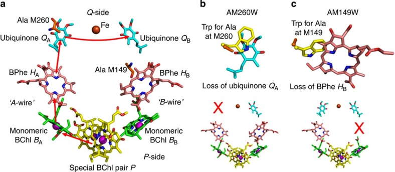
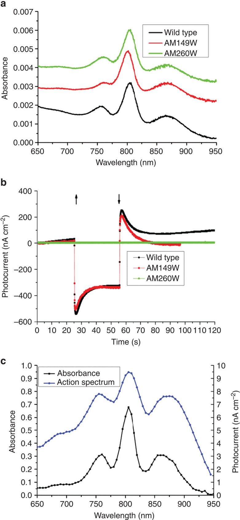
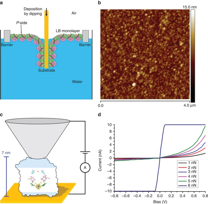
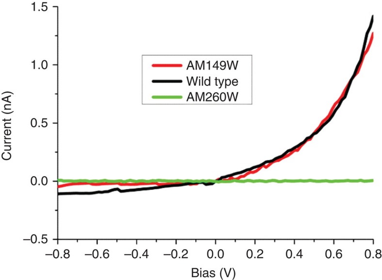
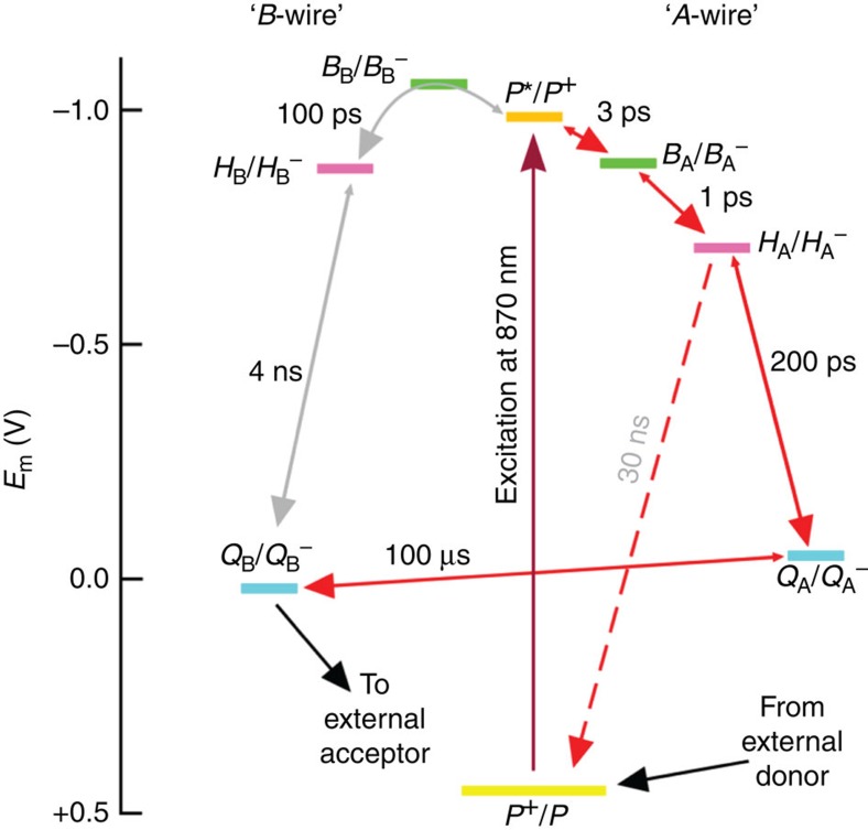
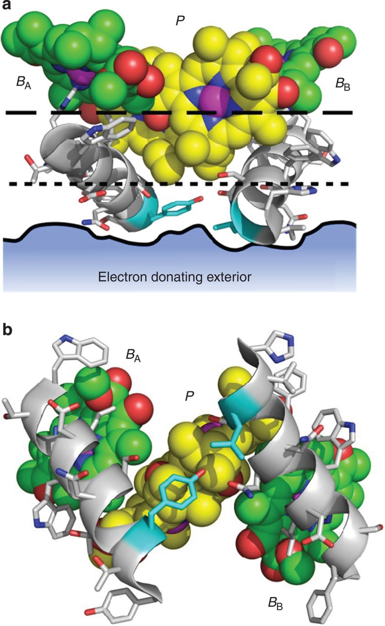
Photosynthetic reaction centres show promise for biomolecular electronics as nanoscale solar-powered batteries and molecular diodes that are amenable to atomic-level re-engineering. In this work the mechanism of electron conduction across the highly tractable Rhodobacter sphaeroides reaction centre is characterized by conductive atomic force microscopy. We find, using engineered proteins of known structure, that only one of the two cofactor wires connecting the positive and negative termini of this reaction centre is capable of conducting unidirectional current under a suitably oriented bias, irrespective of the magnitude of the bias or the applied force at the tunnelling junction. This behaviour, strong functional asymmetry in a largely symmetrical protein-cofactor matrix, recapitulates the strong functional asymmetry characteristic of natural photochemical charge separation, but it is surprising given that the stimulus for electron flow is simply an externally applied bias. Reasons for the electrical resistance displayed by the so-called B-wire of cofactors are explored.


Figures

Figure 1
Figure 1. Structures of wild-type and engineered RCs.
(a) Two wires of cofactors connect the P-side (positive terminus) and Q-side (negative terminus) of the wild-type RC. Photoexcitation of the P dimer triggers electron flow along the A-wire (red arrows) forming, sequentially, P+BA, P+HA and P+QA radical pairs. Electrons exit the complex via the dissociable QB ubiquinone. (b) Overlay of the X-ray crystal structures of the wild-type and AM260W mutant RCs shows that replacement of Ala M260 by Trp prevents incorporation of the QA ubiquinone due to steric overlap (top), breaking the A-wire (bottom). (c) Similarly, replacement of Ala M149 by Trp prevents incorporation of the HB BPhe (top), breaking the B-wire (bottom). Key for all panels: nitrogen—blue, oxygen—red, cofactor carbons—yellow, green, pink or cyan, protein carbons—orange (wild-type RC) or yellow (mutant RC), magnesium—magenta spheres, iron—brown sphere.
Figure 2
Figure 2. Photochronoamperometry of RC-rich membranes.
(a) Absorbance spectra of RC-rich membranes adhered to gold working electrodes. (b) Photocurrent response of coated electrodes during 30 s of illumination (↑—light on,↓—light off). (c) Comparison of absorbance spectrum at 5 nm intervals with the action spectrum of photocurrent density for adhered membranes with wild-type RCs.
Figure 3
Figure 3. Deposition of LB films and conductive AFM.
(a) Schematic of the deposition of an LB monolayer of RC-rich membranes by dipping to achieve a uniform P-side down orientation. (b) Tapping mode AFM of a deposited LB film. (c) Schematic of the conductive AFM measurement; a potential ramp is applied between the AFM tip (not to scale) and the gold substrate at a range of applied tip forces, the tunnelling junction being formed by the RC-rich LB film. The proportion of the RC residing outside the membrane is indicated by shading; the two cofactor wires (shown as in Fig. 1a) span the membrane-embedded region. (d) Current-–voltage profiles for deposited wild-type RCs at varying tip forces.
Figure 4
Figure 4. Tunnelling of electrons across engineered RCs.
Current voltage profiles for wild-type and engineered RCs at an applied tip force of 1 nN.
Figure 5
Figure 5. Redox basis for asymmetric photochemical charge separation.
Plot shows the mid-point potentials of redox couples involved in A-wire photochemical charge separation (right) and equivalent states involving B-wire cofactors (left).
Figure 6
Figure 6. Electron ingress at the P-side of the RC.
(a) The macrocyles of the P, BA and BB BChls are shown as spheres with atom colours as for Fig. 1a. The edges of the macrocycles of the P BChls (marked by the dotted line) are located closer to the surface of the protein (solid line) than those of the BA and BB BChls (dashed line). The solid line shows the boundary of the protein surface in a vertical plane corresponding to the amino acids highlighted with cyan carbons. (b) View from below of the structural elements shown in a. The P BChls are separated from the adjacent aqueous phase by only a single layer of amino acids (highlighted with cyan carbons), whereas the BA and BB Bchls are more deeply buried within the protein, each overlaid by an amphipathic α-helix. Key: nitrogen—blue, oxygen—red, protein carbons—white.

Similar articles

Cited by

References

    1. Davis J. J. et al.. Molecular bioelectronics. J. Mat. Chem. 15, 2160–2174 (2005) .
    1. Ron I., Pecht I., Sheves M. & Cahen D. Proteins as solid-state electronic conductors. Acc. Chem. Res. 43, 945–953 (2010) . - PubMed
    1. Sek S. Peptides and proteins wired into the electrical circuits: An SPM-based approach. Biopolymers 100, 71–81 (2013) . - PubMed
    1. Zhang J. D. et al.. Single-molecule electron transfer in electrochemical environments. Chem. Rev. 108, 2737–2791 (2008) . - PubMed
    1. Nitzan A. & Ratner M. A. Electron transport in molecular wire junctions. Science 300, 1384–1389 (2003) . - PubMed

Publication types

MeSH terms

Substances

LinkOut - more resources