. 2015 Mar 8;471(2175):20140905.
doi: 10.1098/rspa.2014.0905.

The evolution of air resonance power efficiency in the violin and its ancestors

Affiliations

The evolution of air resonance power efficiency in the violin and its ancestors

Hadi T Nia et al. Proc Math Phys Eng Sci. .

Abstract

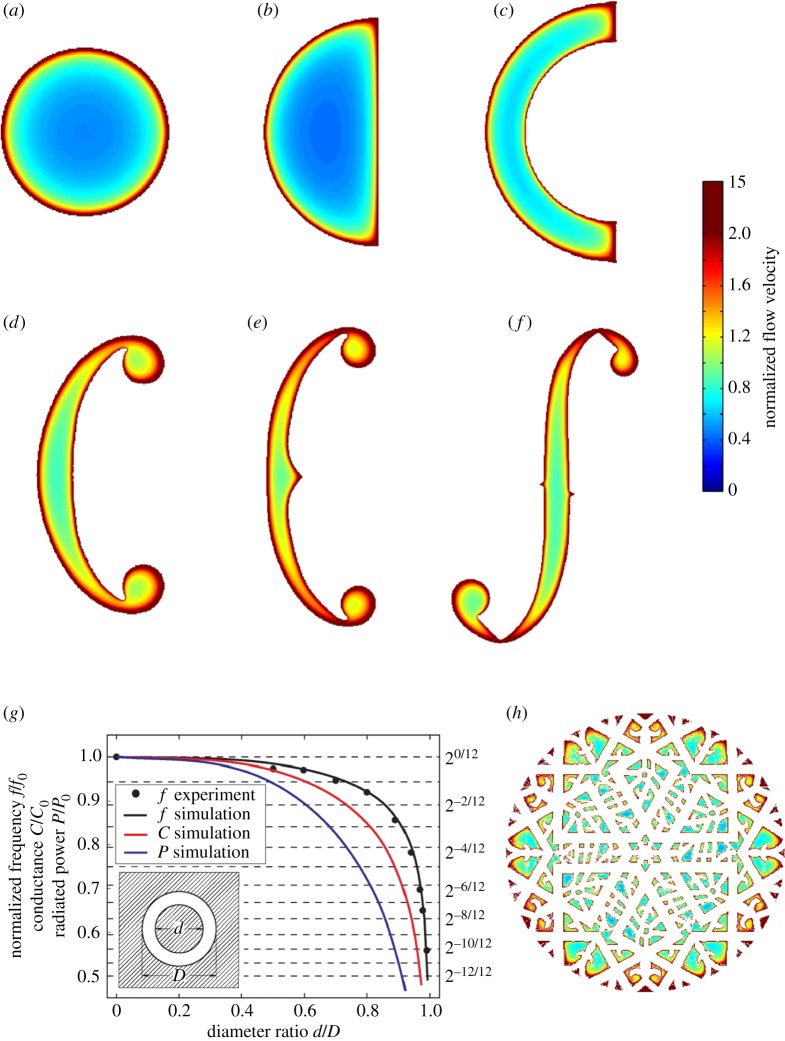
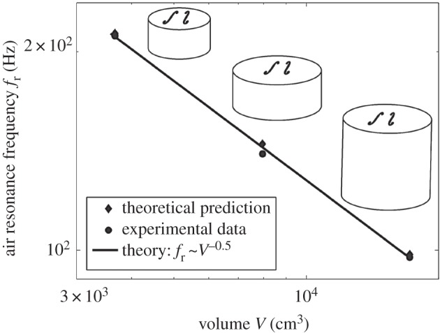
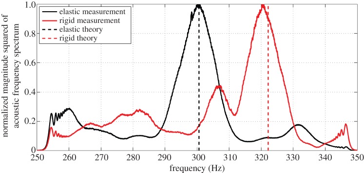
The fact that acoustic radiation from a violin at air-cavity resonance is monopolar and can be determined by pure volume change is used to help explain related aspects of violin design evolution. By determining the acoustic conductance of arbitrarily shaped sound holes, it is found that air flow at the perimeter rather than the broader sound-hole area dominates acoustic conductance, and coupling between compressible air within the violin and its elastic structure lowers the Helmholtz resonance frequency from that found for a corresponding rigid instrument by roughly a semitone. As a result of the former, it is found that as sound-hole geometry of the violin's ancestors slowly evolved over centuries from simple circles to complex f-holes, the ratio of inefficient, acoustically inactive to total sound-hole area was decimated, roughly doubling air-resonance power efficiency. F-hole length then slowly increased by roughly 30% across two centuries in the renowned workshops of Amati, Stradivari and Guarneri, favouring instruments with higher air-resonance power, through a corresponding power increase of roughly 60%. By evolution-rate analysis, these changes are found to be consistent with mutations arising within the range of accidental replication fluctuations from craftsmanship limitations with subsequent selection favouring instruments with higher air-resonance power.

Keywords: Helmholtz resonance; f-hole; musical acoustics; sound hole evolution; violin acoustics; violin evolution.


Figures

Figure 1.
Figure 1.
Acoustic air-resonance power efficiency grows as sound hole shape evolves over centuries through the violin's European ancestors to the violin. (a) Change in radiated acoustic air-resonance power for an elastic instrument Wair-elastic (equation (4.5)), rigid instrument Wair-rigid (equation (4.2)) and infinite rigid sound hole bearing wall Wwall (equation (4.1)) as a function of sound hole shape, where percentage change is measured from the circular sound hole shape. (b) Air-resonance frequency for elastic instrument fair-elastic (equation (4.4)) and rigid instrument fair-rigid (equation (4.3)) as a function of sound hole shape, normalized by fair-elastic for the circular opening (i). (c) Conductance C (equation (2.3)) and perimeter length L for different sound hole shapes of fixed sound-hole area, normalized to be unity for the circular opening (i). Shape overlap occurred between nearby centuries. Only sound hole shape is changed and all other parameters are held fixed and equal to those of the 1703 ‘Emiliani’ Stradivari violin [30]. The conductance of the two interacting sound holes for each instrument is determined from equation (2.3). Data sources are provided in the electronic supplementary material, §5.
Figure 2.
Figure 2.
Sound hole shape evolution driven by maximization of efficient flow near outer perimeter, minimization of inactive sound-hole area and consequent maximization of acoustic conductance. Normal air velocity field un(x,y,z) (equation (2.2)) through (a)–(f) sound holes (i)–(vi) of figure 1 and (h) a lute rosette known as the ‘Warwick Frei’ [32] estimated for an infinite rigid sound hole bearing wall at air-resonance frequencies by boundary element method in §2. (g) Experimental verification and illustration of the sound hole conductance theory for annular sound holes. Dashed horizontal lines indicate equal temperament semitone factors. The resonance frequency, conductance and radiated power of a circular sound hole are represented by f0, C0 and P0, respectively. Velocities in (a)–(f) and (h) are normalized by the average air-flow velocity through the circular sound hole (a).
Figure 3.
Figure 3.
Time series of change in total radiated acoustic power as a function of temporal changes of the purely geometric parameter of f-hole length during the Cremonese period. The estimated dependence via elastic volume flux analysis (Wair-elasticC1.7, equation (4.5), solid coloured lines) is roughly the average of the upper (WwallC2, equation (4.1), dashed black line) and lower (Wair-rigidC, equation (4.2), solid black line) limiting cases. Coloured lines and shaded patches, respectively, represent mean trends and standard deviations of Wair-elastic for different workshops: Amati (blue), Stradivari (red), Guarneri (green), Amati–Stradivari overlap (blue-red) and Stradivari–Guarneri overlap (red-green). Percentage change is measured from the 1560 Amati workshop instrument. The conductance of the two interacting violin f-holes is determined from equation (2.3).
Figure 4.
Figure 4.
Time series of changes in (a) total radiated acoustic air-resonance power Wair-elastic (equation (4.5), solid coloured lines); (b) air resonance frequency fair-elastic (equation (4.4), solid coloured lines) over the classical Cremonese period and (c) f-hole length LF (coloured markers) measured from 470 Cremonese violins. Coloured shaded patches in (a) and (b) represent standard deviations. Filled circles and error bars in (b), respectively, represent the means and standard deviations of air resonance frequencies for each workshop for 26 surviving Cremonese violins (2 Nicolo Amati, 17 Antonio Stradivari, 7 Guarneri del Gesu) previously measured in the literature [–45]. Black solid line in (b) represents rigid instrument air resonance frequency fair-rigid (equation (4.3)). Two northern Italian pitch standards, Mezzo Punto and Tuono Corista (electronic supplementary material, §10), from the late sixteenth to late seventeenth centuries and common seventeenth to early eighteenth centuries French baroque pitches (black dashed lines) are also shown in (b). Percentage change in radiated power is measured from the 1560 Amati workshop instrument. Black line in (c) represents 10-instrument running average. The conductance of the two interacting violin f-holes is determined from equation (2.3). Data sources are provided in the electronic supplementary material, §5. *Documents suggest Tutto Punto to be the problematic pitch of the Cremonese organ in 1583 because it did not conform to dominant Northern Italian pitch standards of the time (electronic supplementary material, §10).
Figure 5.
Figure 5.
Temporal variations in (a) air-cavity volume V , (b) back plate thickness hback, (c) top plate thickness htop (d) plate thickness near f-holes hsh and (e) mean air cavity height ha measured from 110 classical Cremonese violins. Black lines in (a,e) represent 20-instrument running averages, and in (b)–(d) represent quadratic regression fits of available thickness data. Data sources are provided in the electronic supplementary material, §5.
Figure 6.
Figure 6.
Approximate components of temporal trends in (a) radiated acoustic power Wair-elastic (equation (4.5)) and (b) air resonance frequency fair-elastic (equation (4.4)) over time due to f-hole length LF (blue), air cavity volume V (red), top plate thickness htop (green), back plate thickness hback (magenta), plate thickness near f-hole hsh (brown) and mean air cavity height ha (yellow) estimated from elastic analysis. Mean trends and standard deviations are represented by coloured solid lines and error bars, respectively. Percentage change in radiated power is measured from the 1560 Amati workshop instrument. Contributions from each parameter are isolated by holding all other parameters fixed at 1560 Amati workshop instrument values. The conductance of the two interacting violin f-holes is determined from equation (2.3). Input mean time series data are from figures 4c and 5.
Figure 7.
Figure 7.
Measured evolution rates and thresholds distinguishing mutation origins as being consistent or inconsistent with accidental replication fluctuations from craftsmanship limitations. Mean evolution rates for (a) linear sound hole dimension and (b) estimated radiated acoustic power at air resonance. Below N=2, corresponding to ECraftFluct (equation (6.1), lower dashed grey line), mutations likely arise within the range of accidental replication fluctuations due to craftsmanship limitations. Above N≈4, corresponding to EDesignPlan (equation (6.2), upper dashed grey line), mutations probably arise from planned design changes. All rates are based on a generational period of 0.1 year (electronic supplementary material, §5).
Figure 8.
Figure 8.
Sound hole shapes and violins made by Savart and Chanot in the early 1800s [–51]. While the Savart and Chanot instruments, which had notable design differences from classical violins, were unsuccessful, they were made for the violin repertoire and were consistently referred to as violins by their creators and in subsequent literature [–51]. In particular, Savart's instrument is usually referred to as the ‘trapezoidal’ violin and Chanot's instrument is usually referred to as the ‘guitar-shaped’ violin [6,50,51].
Figure 9.
Figure 9.
Experimental verification of theoretical f-hole conductance. Theoretical boundary element method predictions (diamonds) and experimental measurements (circles) of air-resonance frequency show excellent agreement (RMSE ≈ 1%). A receiver is placed inside an instrument with rigidly clamped walls. An acoustical source is placed outside the instrument. Expected V −0.5 dependence of the air resonance frequency for a rigid instrument is observed. The conductance of the two interacting violin f-holes is determined from equation (2.3) in theoretical predictions. The air-resonance frequency is taken to be the average of the half-power frequencies measured on either side of the air-resonance peak and is found to have insignificant variation of less than 1% across multiple measurements.
Figure 10.
Figure 10.
Conductance-based theory accurately estimates (RMSE ≈ 1%) Helmholtz resonance frequencies for various sound hole shapes. By contrast, resonance frequencies are incorrectly estimated from the circle-of-same-area approach. The conductance of the interacting sound holes of any instrument with multiple sound holes is determined from equation (2.3). The air-resonance frequency is taken to be the average of the half-power frequencies measured on either side of the air-resonance peak and is found to have insignificant variation of less than 1% across multiple measurements.
Figure 11.
Figure 11.
The measured Helmholtz resonance frequency of a violin with rigidly clamped top and back plates (solid red curve) is an excellent match (within roughly 1%) to the rigid instrument analysis (equation (4.3), dashed red line). When the plate clamps are removed, the measured resonance frequency (solid black curve) reduces by roughly 6% or a semitone, consistent with the reduction expected from elastic volume flux analysis for the violin (dashed black line). The two spectra shown are normalized by their respective peak amplitudes. The violin is externally stimulated with white noise. The violin used here has LF=70.5 mm, V =1580 cm3, hsh=2.7 mm, ha=35.9 mm, htop=2.5 mm and hback=3 mm. Other physical parameters are given in table 1.

References

    1. Meyer J. 1972. Directivity of the bowed stringed instruments and its effect on orchestral sound in concert halls. J. Acoust. Soc. Am. 51, 1994–2009 (doi:10.1121/1.1913060) - DOI
    1. Lighthill J. 1978. Waves in fluids. Cambridge, UK: Cambridge University Press.
    1. Rayleigh BJWS. 1896. The theory of sound, vol. 2 London, UK: Macmillan and Co.
    1. Lamb H. 1925. The dynamical theory of sound. New York, NY: Dover Publications Inc.
    1. Helmholtz H. 1877. On the sensations of tone. [Trans. AJ Ellis] New York, NY: Dover.

LinkOut - more resources