. 2015 Apr 16;58(2):216-31.
doi: 10.1016/j.molcel.2015.02.023. Epub 2015 Mar 26.

Widespread rearrangement of 3D chromatin organization underlies polycomb-mediated stress-induced silencing

Affiliations

Widespread rearrangement of 3D chromatin organization underlies polycomb-mediated stress-induced silencing

Li Li et al. Mol Cell. .

Abstract

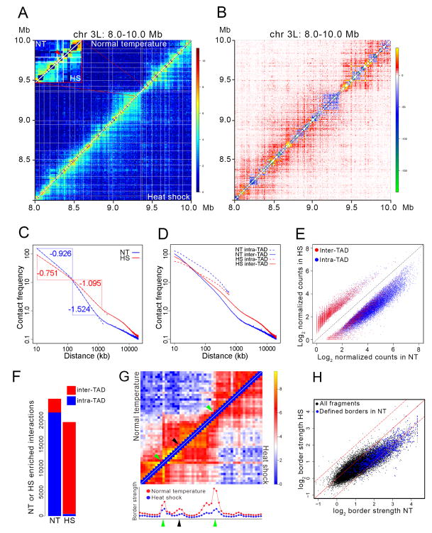
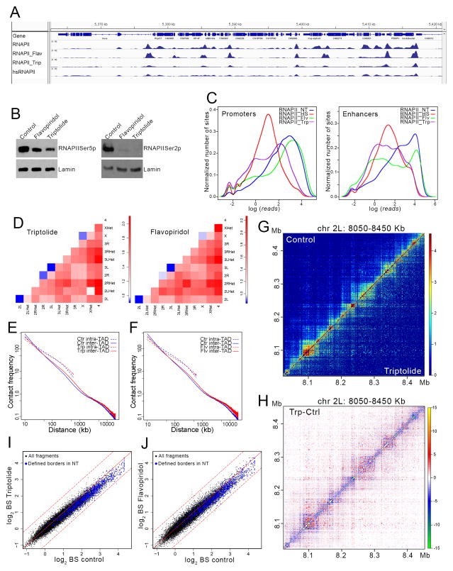
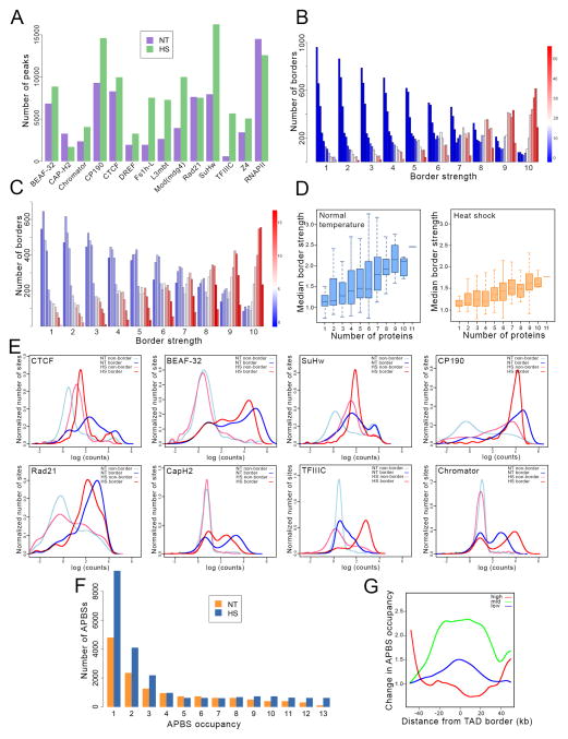
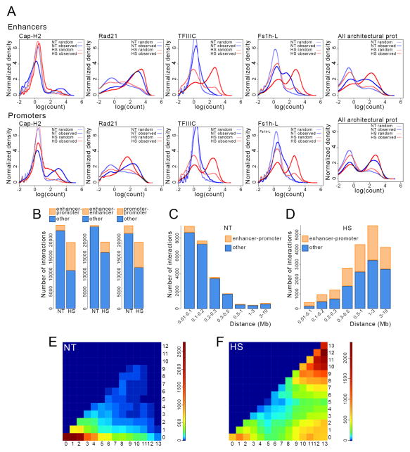
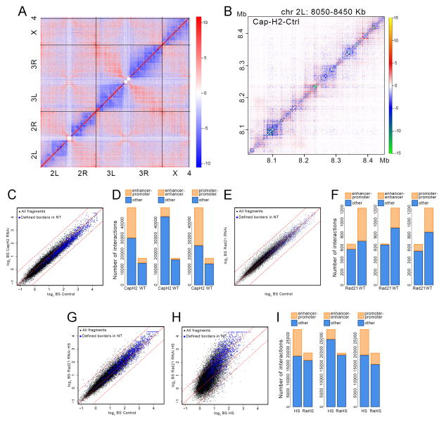
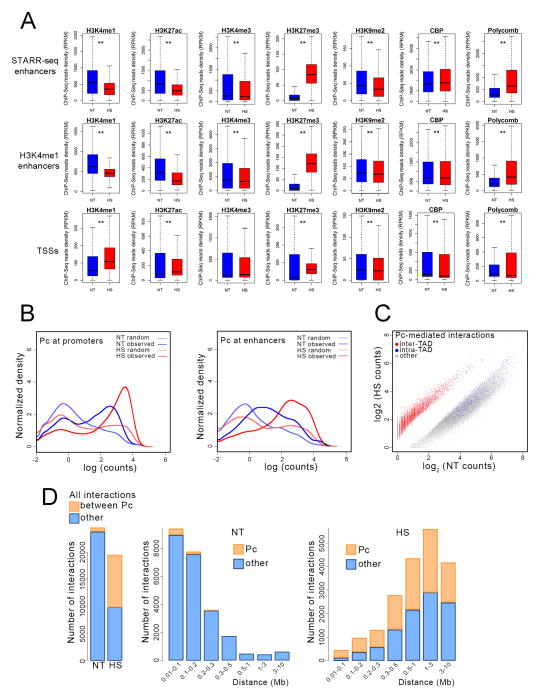
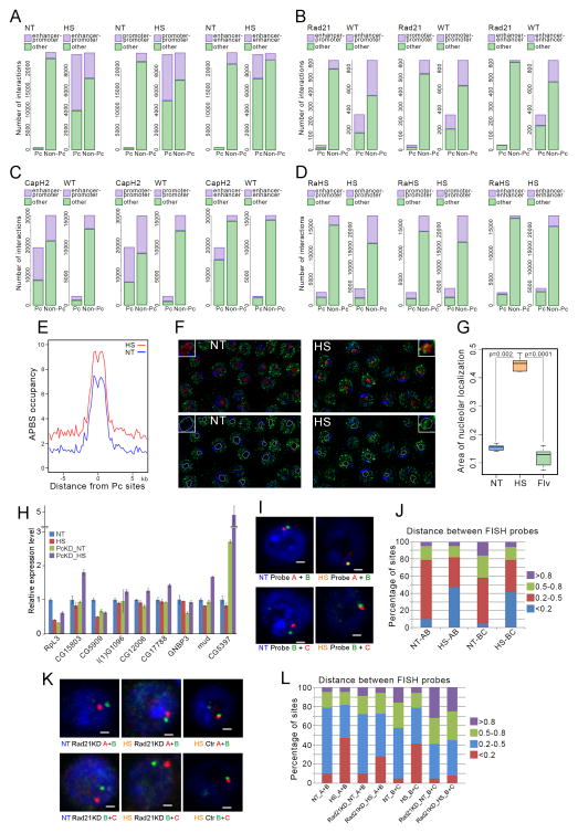
Chromosomes of metazoan organisms are partitioned in the interphase nucleus into discrete topologically associating domains (TADs). Borders between TADs are formed in regions containing active genes and clusters of architectural protein binding sites. The transcription of most genes is repressed after temperature stress in Drosophila. Here we show that temperature stress induces relocalization of architectural proteins from TAD borders to inside TADs, and this is accompanied by a dramatic rearrangement in the 3D organization of the nucleus. TAD border strength declines, allowing for an increase in long-distance inter-TAD interactions. Similar but quantitatively weaker effects are observed upon inhibition of transcription or depletion of individual architectural proteins. Heat shock-induced inter-TAD interactions result in increased contacts among enhancers and promoters of silenced genes, which recruit Pc and form Pc bodies in the nucleolus. These results suggest that the TAD organization of metazoan genomes is plastic and can be reconfigured quickly.


Figures

Figure 1
Figure 1. Changes in TAD organization after heat shock
(A) Hi-C contact maps at single fragment resolution for control (upper left) and heat shock (lower right) Kc167 cells plotted with normalized intra-chromosomal arm read pairs in a 2 Mb region of chromosome 3L. White lines denote TAD borders in control cells. Inset shows an enlargement of a 34-HindIII fragment region of chromosome 3L containing several heat shock genes within a 16 kb interval; red arrow indicates the location of these genes. (B) Subtraction of normal temperature control from heat shock contact matrices shows changes in contact frequencies between the two Hi-C samples. Region of chromosome 3L depicted is the same as in Figure 1A. (C) Intra-chromosome arm chromatin contact frequency decay curves of control (NT, blue) and heat shock (HS, red) Hi-C data. Point of intersection between the vertical blue and horizontal red lines is located at 140 kb. (D) Intra-chromosome arm chromatin contact frequency decay curves of control (NT, blue) and heat shock (HS, red) for intra- and inter-TAD interactions. (E) Scatter plot of intra- and inter-TAD contact frequencies of control-specific (NT) and heat shock-specific (HS) interactions. Interactions were calculated based on counts present in 5 kb bins. Diagonal dashed black line shows the result assuming there is no difference in intra- or inter-TAD contacts between NT and HS. (F) Number of intra- and inter-TAD interactions specific for the control (NT) and heat shock (HS) Hi-C data sets. (G) Contact matrices of a ~200 kb region from cells grown at normal temperature (upper left) or heat shocked (lower right) at single fragment resolution. Green arrows indicate the location of TAD borders determined computationally. Black arrow indicates the location of a sub-TAD border determined visually. Graphs below the heat maps indicate the border strength for each restriction fragment shown in the heat maps above. Red and blue dots indicate border strength in arbitrary units in control and heat shocked cells, respectively. (H) Scatter plot comparing TAD border strength in control (NT) and heat shock (HS) Hi-C samples. Blue dots indicate border strength for TAD borders determined using a probability-based model. Black dots indicate border strength for all HindIII restriction fragments in the genome. Dashed lines above and below the diagonal indicate + or − one standard deviation, respectively. See also Figure S1.
Figure 2
Figure 2. Effect of transcription inhibition on 3D organization
(A) Screenshot of a region of the Drosophila genome showing ChIP-seq signal for RNAPII in control, flavopiridol-treated, triptolide-treated, and heat shocked cells. (B) Western analysis of control, flavopiridol-treated and triptolide-treated cells using antibodies to the CTCD domain of RNAPII phosphorylated in serine 5 (left) or serine 2 (right). Antibodies to lamin were used for the loading control (bottom). (C) Distribution of ChIP-seq normalized reads with respect to sites in the genome at enhancers and promoters in cells grown at normal temperature, heat shocked, and treated with tripdolide or flavopiridol. (D) Changes in frequency of intra- and inter-arm interactions obtained from Hi-C data in cells treated with triptolide or flavopiridol relative to untreated cells. (E) Decay curves of intra- and inter-TAD interactions with respect to distance for control and triptolide-treated cells. (F) Decay curves of intra- and inter-TAD interactions with respect to distance for control and flavopiridol-treated cells. (G) Two-dimensional contact matrices of Hi-C data obtained with control (upper left) and triptolide-treated (bottom right) cells. (H) Subtraction heat map in which the contact matrix for a 400 kb of chromosome 2L obtained from Hi-C data in control cells has been subtracted from that obtained in triptolide-treated cells. (I) Scatter plot comparing border strength (BS) in Hi-C samples from control and triptolide-treated cells. Blue dots indicate TAD borders determined using a probability-based model. Black dots indicate all DpnII restriction fragments in the genome. Dashed lines above and below the diagonal indicate + or − one standard deviation, respectively. (J) Scatter plot comparing border strength (BS) in Hi-C samples from control and flavopiridol-treated cells. Blue dots indicate TAD borders determined using a probability-based model. Black dots indicate all DpnII restriction fragments in the genome. Dashed lines above and below the diagonal indicate + or − one standard deviation, respectively.
Figure 3
Figure 3. Genome-wide redistribution of architectural proteins during heat shock
(A) Number of ChIP-seq peaks for different architectural proteins and RNAPII in control (NT) and heat shocked (HS) cells. (B) Number of borders found in Hi-C data from control cells for each border strength, which ranges from 1 to 10 in arbitrary units. For each border strength, the number of borders containing different amounts of RNAPII (red to blue) and APBSs occupied with different numbers of architectural proteins (12 columns for each border strength ranging in occupancy from 1 to 12 from left to right). Color bar for RNAPII indicates number of mapped ChIP-seq reads in 50 bp bins normalized relative to the total number of reads. (C) Number of borders found in Hi-C data from heat shocked cells for each border strength, which ranges from 1 to 10 in arbitrary units. For each border strength, the number of borders containing different amounts of RNAPII (red to blue) and APBSs occupied with different numbers of architectural proteins (12 columns for each border strength ranging in occupancy from 1 to 12 from left to right). (D) Box plots indicating the relationship between median border strength and the number of architectural proteins present at each border for control (left) and heat shocked (right) cells. (E) Relationship between the normalized number of sites in the genome and the number of normalized ChIP-seq reads for different architectural proteins at TAD borders and non-borders in control and heat shocked cells. (F) Change in the number of architectural protein binding sites (APBSs) with different numbers of architectural proteins (APBS occupancy) in heat shocked (HS) with respect to control (NT) cells. (G) Changes in APBS occupancy with respect to the distance from TAD borders for TAD borders with low (1–4) mid (5–8) and high (9–13) number of architectural proteins in heat shocked cells with respect to control.
Figure 4
Figure 4. Changes in enhancer-promoter interactions in heat shocked cells
(A) Relationship between the number of sites and the ChIP-seq read count for various architectural proteins in control and heat shocked cells at enhancers and promoters. (B) Changes in the number of interactions among enhancers and promoters in heat shocked (HS) with respect to control (NT) cells. (C) Number of interactions at different distances for enhancer-promoter contacts in cells grown at normal temperature (NT). (D) Number of interactions at different distances for enhancer-promoter contacts in heat shocked cells (HS). (E) Frequency of interactions between enhancers and promoters containing different numbers (1–13) of architectural proteins in cells grown at normal temperature (NT). (F) Frequency of interactions between enhancers and promoters containing different numbers (1–13) of architectural proteins in cells subjected to temperature stress (HS). See also Figure S2.
Figure 5
Figure 5. Effect of Cap-H2 and Rad21 depletion on 3D chromatin organization
(A) Whole genome heat map obtained by subtracting the two dimensional contact matrix of Hi-C data from control cells from that of Cap-H2 depleted cells. Black vertical and horizontal lines indicate chromosome boundaries. (B) Heat map for a 400 kb region of chromosome 2L obtained by subtracting the two dimensional contact matrix of Hi-C data from control cells from that of Cap-H2 depleted cells. (C) Scatter plot comparing border strength (BS) in Hi-C samples from control and Cap-H2 depleted cells. Blue dots indicate TAD borders determined using a probability-based model. Black dots indicate all DpnII restriction fragments in the genome. Dashed lines above and below the diagonal indicate + or − one standard deviation, respectively. (D) Number of interactions among enhancers and promoters specific for normal (WT) and Cap-H2-depleted (CapH2) cells. (E) Scatter plot comparing border strength (BS) in Hi-C samples from control and Rad21 depleted cells. Symbols are as in panel C. (F) Number of interactions among enhancers and promoters specific for normal (WT) and Rad21-depleted (Rad21) cells. (G) Scatter plot comparing border strength in Hi-C samples from control and Rad21 depleted cells subjected to heat shock. Symbols are as in panel C. (H) Scatter plot comparing border strength in Hi-C samples from normal control and Rad21 depleted cells, both subjected to heat shock. Symbols are as in panel C. (I) Number of interactions among enhancers and promoters specific for heat shocked (HS) and Rad21-depleted cells subjected to heat shock (RaHS). See also Figure S3.
Figure 6
Figure 6. Changes in histone modifications and chromatin proteins in heat shocked cells
(A) Box plots indicating changes in the levels of various histone modifications and chromatin proteins at enhancers and promoters of control (blue) versus heat shocked (red) cells. ** indicates p<0.001 (B) Changes in the number of Pc sites at enhancers and promoters and the read number at each site in control (NT) versus heat shocked (HS) cells. (C) Scatter plot showing changes in intra- and inter-TAD interactions between DNA fragments containing Pc in control (NT) versus heat shocked (HS) cells. (D) Changes in the number of interactions and the distance between the interacting Pc-containing DNA fragments in control (NT) versus heat shocked (HS) cells. See also Figure S4
Figure 7
Figure 7. Analysis of Pc-mediated interactions by Hi-C and FISH
(A) Number of interactions among Pc-containing enhancers and promoters in control (NT) and heat shocked (HS) cells. (B) Number of interactions among enhancers and promoters specific for normal (WT) and Rad21-depleted (Rad21) cells. (C) Number of interactions among enhancers and promoters specific for normal (WT) and Cap-H2-depleted (CapH2) cells. (D) Number of interactions among enhancers and promoters specific for normal (HS) and Rad21-depleted (RaHS) cells, both subjected to heat shock. (E) Distribution of APBSs with different occupancies around Pc sites in control and heat shocked cells (F) Immunofluorescence microscopy of control (NT) and heat shocked (HS) cells stained with antibodies to Pc (green) and fibrillarin (red, nucleolus); DAPI is indicated in blue. The location of the nucleolus has been traced with a white line in the lower panels based on the location of fibrillarin signal. Insets show an enlarged region containing the nucleolus from one of the cells. (G) Box plots showing levels of Pc protein in the nucleolar region of control (NT), heat shocked (HS) and flavopiridol-treated (Flv) cells. (H) RNA expression levels of nine different genes under different experimental conditions. NT denotes control cells grown at normal temperature and HS indicates control cells subjected to heat shock at 36.5 C for 20 min. PcKD denotes cells depleted of Pc by RNAi and grown at normal temperature (PcKD_NT) or subjected to heat shock (PcKD_HS). (I) FISH using three Pc-containing DNA fragments, A, B and C, shown to interact by Hi-C. NT denotes cells grown at normal temperature and HS indicates cells heat shocked at 36.5 °C. White bar indicates 1 μm. (J) Analysis of distances between FISH probes using cells grown at normal temperature (NT) or subjected to heat shock (HS). Distances are indicated in μm. (K) FISH using three Pc-containing DNA fragments, A, B and C, shown to interact by Hi-C. NT denotes cells grown at normal temperature and HS indicates cells heat shocked at 36.5 °C. White bar indicates 1 μm. Rad21KD denotes cells depleted of Rad21 by RNAi and Ctr indicates untreated control cells. (L) Analysis of distances between FISH probes using control or Rad21 depleted (Rad21KD) cells grown at normal temperature (NT) or subjected to heat shock (HS). Distances are indicated in μm. See also Figure S3.

References

    1. Bauer CR, Hartl TA, Bosco G. Condensin II promotes the formation of chromosome territories by inducing axial compaction of polyploid interphase chromosomes. PLoS genetics. 2012;8:e1002873. - PMC - PubMed
    1. Bonora G, Plath K, Denholtz M. A mechanistic link between gene regulation and genome architecture in mammalian development. Current opinion in genetics & development. 2014;27:92–101. - PMC - PubMed
    1. Cheutin T, Cavalli G. Polycomb silencing: from linear chromatin domains to 3D chromosome folding. Current opinion in genetics & development. 2014;25:30–37. - PubMed
    1. D’Ambrosio C, Schmidt CK, Katou Y, Kelly G, Itoh T, Shirahige K, Uhlmann F. Identification of cis-acting sites for condensin loading onto budding yeast chromosomes. Genes & development. 2008;22:2215–2227. - PMC - PubMed
    1. Delest A, Sexton T, Cavalli G. Polycomb: a paradigm for genome organization from one to three dimensions. Current opinion in cell biology. 2012;24:405–414. - PubMed

Publication types

MeSH terms