. 2015 Apr 6;5(2):20140079.
doi: 10.1098/rsfs.2014.0079.

A multiscale model for the study of cardiac biomechanics in single-ventricle surgeries: a clinical case

Affiliations

A multiscale model for the study of cardiac biomechanics in single-ventricle surgeries: a clinical case

Alessio Meoli et al. Interface Focus. .

Abstract

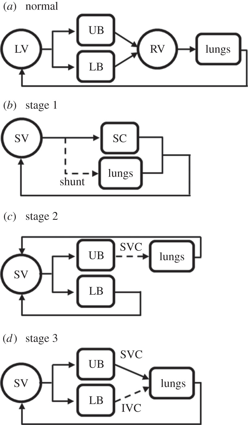
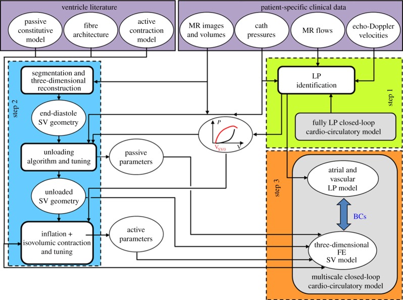
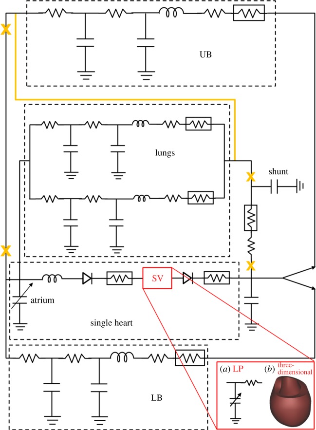
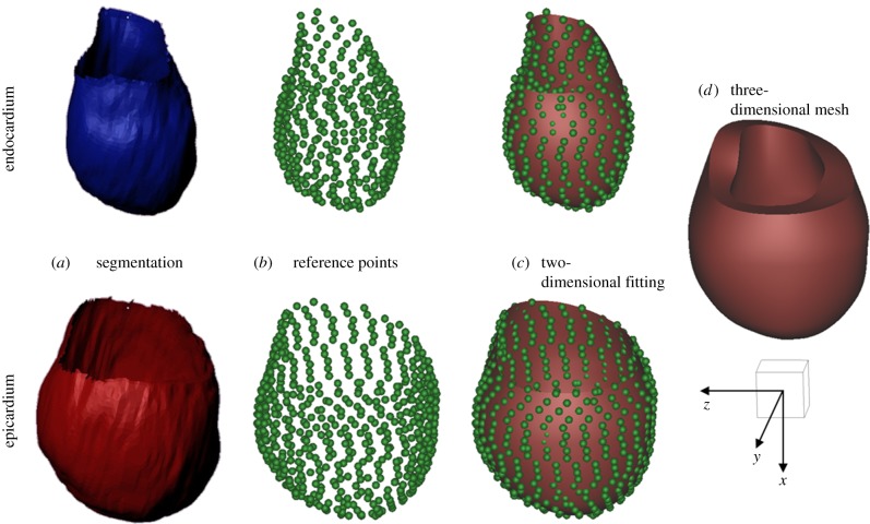
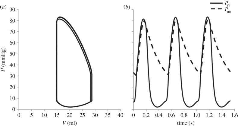
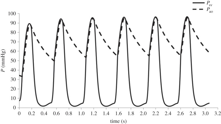
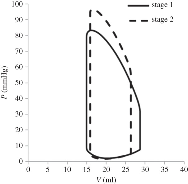
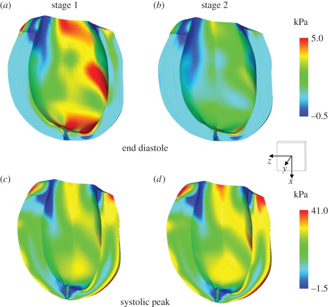
Complex congenital heart disease characterized by the underdevelopment of one ventricular chamber (single ventricle (SV) circulation) is normally treated with a three-stage surgical repair. This study aims at developing a multiscale computational framework able to couple a patient-specific three-dimensional finite-element model of the SV to a patient-specific lumped parameter (LP) model of the whole circulation, in a closed-loop fashion. A sequential approach was carried out: (i) cardiocirculatory parameters were estimated by using a fully LP model; (ii) ventricular material parameters and unloaded geometry were identified by means of the stand-alone, three-dimensional model of the SV; and (iii) the three-dimensional model of SV was coupled to the LP model of the circulation, thus closing the loop and creating a multiscale model. Once the patient-specific multiscale model was set using pre-operative clinical data, the virtual surgery was performed, and the post-operative conditions were simulated. This approach allows the analysis of local information on ventricular function as well as global parameters of the cardiovascular system. This methodology is generally applicable to patients suffering from SV disease for surgical planning at different stages of treatment. As an example, a clinical case from stage 1 to stage 2 is considered here.

Keywords: finite-element method; lumped parameter model; multiscale coupling; single ventricle heart; virtual surgery.


Figures

Figure 1.
Figure 1.
Sketches of normal (a) and pathological circulations (bd). (b) In parallel Norwood circulation (stage 1), with the interposition of a systemic-to-pulmonary shunt to deliver blood to the lungs; (c) stage 2 circulation with the upper systemic and pulmonary circulations in series; and (d) stage 3 Fontan circulation, with the systemic and pulmonary circulations in series. IVC, inferior vena cava; LB, lower body; LV, left ventricle; RV, right ventricle; SC, systemic circulation; SV, single ventricle; SVC, superior vena cava; UB, upper body.
Figure 2.
Figure 2.
Workflow of the sequential approach adopted in this study. The parameter estimation of the cardio-circulatory model was performed by means of a fully LP closed-loop model (step 1, green box). The three-dimensional ventricular geometry of the patient was reconstructed from MR images and the myocardial parameters (passive and active models and unloaded geometry) were estimated considering the stand-alone three-dimensional FE model of SV (step 2, blue box). A multiscale closed-loop cardio-circulatory model was created by coupling the LP circulatory model to the three-dimensional FE model (step 3, orange box). Literature information combined with patient-specific clinical data were used during step 1 and step 2 (violet box). (Online version in colour.)
Figure 3.
Figure 3.
Patient-specific biomechanical model for stage 1 and stage 2. The circulatory layout of stage 1 (continuous black lines) comprised the single heart, the systemic upper body (UB), lower body (LB) and lungs circulations and the shunt. After the stage 2 surgery, the shunt was removed and the UB circulation connected in series to the pulmonary circulation. Changes in the circulatory layout after stage 2 are shown in orange. The single ventricle was modelled as a time-varying elastance in series with a linear resistance for the LP model (red box (a)) to perform parameters identification. To obtain the multiscale model of both stage 1 and stage 2 conditions, the LP model of the SV was replaced by the three-dimensional FE model (red box (b)). (Online version in colour.)
Figure 4.
Figure 4.
Scheme of the mesh development: (a) segmentation of the endocardial and epicardial surfaces of the SV at end-diastole; (b) identification of the reference points lying of the endocardial and epicardial surfaces; (c) fitting of the two-dimensional cubic-Hermite template mesh to the reference points; and (d) final three-dimensional mesh of the single ventricle (120 nodes and 64 elements). A scale cube (1 cm3) and the Cartesian coordinate system are shown. (Online version in colour.)
Figure 5.
Figure 5.
Haemodynamic results of the stage 1 multiscale model for three consecutive cardiac cycles. (a) Pressure–volume loop; and (b) pressure tracings of the single ventricle (Psv, solid) and the aorta (Pao, dashed).
Figure 6.
Figure 6.
Multiscale model pressure tracings of the single ventricle (Psv, solid) and the aorta (Pao, dashed) for six consecutive cardiac cycles after the circulatory layout was changed from stage 1 to stage 2 to simulate the surgical procedure.
Figure 7.
Figure 7.
Comparison between the pre-operatory and post-operatory pressure–volume loops obtained from the multiscale model.
Figure 8.
Figure 8.
Stress distributions in the fibre direction (kPa) at end-diastole (a,b) and at systolic peak (c,d) for the pre-operatory (stage 1) and post-operatory (stage 2) conditions obtained from the multiscale model. A scale cube (1 cm3) and the Cartesian coordinate system are shown. (Online version in colour.)
Figure 9.
Figure 9.
Strain pattern in the fibre direction for the stage 1 and stage 2 obtained from the multiscale model. The colour map (upper panels) shows the fibre strain at end-diastole. The time profile of the myocardial strains (lower panels) at different locations (points at epicardial (epi) and endocardium (endo) middle cross section and at the apex (apex)) are shown. The solid lines indicate the stage 1 results, whereas the dashed lines refer to stage 2 results. A scale cube (1 cm3) and the Cartesian coordinate system are shown. (Online version in colour.)

References

    1. de Leval MR, Deanfield JE. 2010. Four decades of Fontan palliation. Nat. Rev. Cardiol. 7, 520–527. (10.1038/nrcardio.2010.99) - DOI - PubMed
    1. Algra SO, Breur JMPJ, Evens FCM, de Roo F, Schoof PH, Haas F. 2011. Improving surgical outcome following the Norwood procedure. Neth. Heart J. 19, 369–372. (10.1007/s12471-011-0171-8) - DOI - PMC - PubMed
    1. Feinstein JA, et al. 2012. Hypoplastic left heart syndrome: current considerations and expectations. J. Am. Coll. Cardiol. 59, 1–42. (10.1016/j.jacc.2011.09.022.) - DOI - PMC - PubMed
    1. De Zélicourt DA, Pekkan K, Parks J, Kanter K, Fogel M, Yoganathan AP. 2006. Flow study of an extracardiac connection with persistent left superior vena cava. J. Thorac. Cardiovasc. Surg. 131, 785–791. (10.1016/j.jtcvs.2005.11.031) - DOI - PubMed
    1. Pekkan K, Whited B, Kanter K, Sharma S, De Zélicourt DA, Sundareswaran K, Frakes D, Rossignac J, Yoganathan AP. 2008. Patient-specific surgical planning and hemodynamic computational fluid dynamics optimization through free-form haptic anatomy editing tool (SURGEM). Med. Biol. Eng. Comput. 46, 1139–1152. (10.1007/s11517-008-0377-0) - DOI - PubMed

LinkOut - more resources