. 2015 Apr 20:6:6939.
doi: 10.1038/ncomms7939.

Real-time tunable lasing from plasmonic nanocavity arrays

Affiliations

Real-time tunable lasing from plasmonic nanocavity arrays

Ankun Yang et al. Nat Commun. .

Abstract

Plasmon lasers can support ultrasmall mode confinement and ultrafast dynamics with device feature sizes below the diffraction limit. However, most plasmon-based nanolasers rely on solid gain materials (inorganic semiconducting nanowire or organic dye in a solid matrix) that preclude the possibility of dynamic tuning. Here we report an approach to achieve real-time, tunable lattice plasmon lasing based on arrays of gold nanoparticles and liquid gain materials. Optically pumped arrays of gold nanoparticles surrounded by liquid dye molecules exhibit lasing emission that can be tuned as a function of the dielectric environment. Wavelength-dependent time-resolved experiments show distinct lifetime characteristics below and above the lasing threshold. By integrating gold nanoparticle arrays within microfluidic channels and flowing in liquid gain materials with different refractive indices, we achieve dynamic tuning of the plasmon lasing wavelength. Tunable lattice plasmon lasers offer prospects to enhance and detect weak physical and chemical processes on the nanoscale in real time.


Figures

Figure 1
Figure 1. Lasing emission of Au NP arrays on fused silica with IR-140 in DMSO as superstrate.
(a) Scheme of a lasing device and scanning electron microscopic image of Au NP arrays. Lasing devices consist of Au NP arrays on transparent substrates sandwiched between IR-140 dissolved in an organic solvent and a glass coverslip. Scale bar, 400 nm. (b) Lasing observed at the band edge where the IR-140 photoluminescence (PL) in DMSO overlapped with the lattice plasmon resonance. (c) Input–output of the lasing emission. (inset) Output intensity as a function of the pump energy. (Note: the different lasing wavelengths for b and c were from measurements on two different samples.) (d) (left) Measured far-field beam profiles when the Au NP arrays were pumped with polarization along the high-symmetry direction and (right) 45° with respect to the high-symmetry direction. The insets indicate polarization of the pump beam with respect to the Au NP arrays.
Figure 2
Figure 2. Time-correlated single-photon counting shows lifetime reduction above the lasing threshold.
(a) Decay times measured at pump intensities below and above threshold show a reduction in lifetime around threshold (0.1 mJ cm−2) for the 865-nm lasing mode. The solid lines are fits to the data deconvolved with the instrument response function (IRF). (b) Lifetime map as a function of emission wavelength collected normal to the sample surface above threshold at 0.144 mJ cm−2. The scale bar indicates emitted photon intensity, increasing from blue to red. The cross-section indicated by the dashed line is shown in red in a.
Figure 3
Figure 3. Au NP arrays with tunable lattice plasmon resonances by changing refractive index.
(a) The fabrication technique consists of (i) producing substrates polyurethane (PU) on glass (denoted as PU/glass) with different refractive indices by stripping PU against Si; (ii) floating Cu hole arrays onto PU/glass; (iii) depositing Au; and (iv) etching Cu hole arrays. (b) Scanning electron microscope image of Au NPs on PU/glass. (c) Transmission experiments and (d) simulations of Au NPs in different dielectric environments (n=1.44, 1.48 and 1.52).
Figure 4
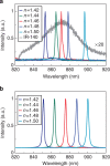
Figure 4. Lasing emission at different wavelengths.
(a) Experiments and (b) simulations of lasing emission from Au NP arrays embedded in different index environments from n=1.42 to n=1.50 (gain concentration: 1 mM; pump intensity: 0.188 mJ cm−2). The emission intensities were normalized.
Figure 5
Figure 5. Lasing emissions from Au NP arrays tuned in real time.
(a) Scheme of the dynamic laser, (b) photograph of the device, (c) switching lasing wavelengths and (d) shifting lasing wavelengths. In c, IR-140 dye molecules were dissolved in DMSO (blue) and BA (red). In d, IR-140 dye molecules were dissolved in DMSO (blue), DMSO: BA=2:1 (red), DMSO: BA=1:2 (purple) and BA (black). DMSO: dimethyl sulfoxide, BA: benzyl alcohol. The emission intensities were normalized.

References

    1. Psaltis D., Quake S. R. & Yang C. Developing optofluidic technology through the fusion of microfluidics and optics. Nature 442, 381–386 (2006). - PubMed
    1. Monat C., Domachuk P. & Eggleton B. J. Integrated optofluidics: a new river of light. Nat. Photon. 1, 106–114 (2007).
    1. Gersborg-Hansen M. & Kristensen A. Tunability of optofluidic distributed feedback dye lasers. Opt. Express 15, 137–142 (2007). - PubMed
    1. Heliotis G. et al., Two-dimensional distributed feedback lasers using a broadband, red polyfluorene gain medium. J. Appl. Phys. 96, 6959–6965 (2004).
    1. Englund D., Altug H., Ellis B. & Vučković J. Ultrafast photonic crystal lasers. Laser Photon. Rev. 2, 264–274 (2008).

Publication types