Quantum Hall resistance standards from graphene grown by chemical vapour deposition on silicon carbide
- PMID: 25891533
- PMCID: PMC4410644
- DOI: 10.1038/ncomms7806
Quantum Hall resistance standards from graphene grown by chemical vapour deposition on silicon carbide
Abstract
Replacing GaAs by graphene to realize more practical quantum Hall resistance standards (QHRS), accurate to within 10(-9) in relative value, but operating at lower magnetic fields than 10 T, is an ongoing goal in metrology. To date, the required accuracy has been reported, only few times, in graphene grown on SiC by Si sublimation, under higher magnetic fields. Here, we report on a graphene device grown by chemical vapour deposition on SiC, which demonstrates such accuracies of the Hall resistance from 10 T up to 19 T at 1.4 K. This is explained by a quantum Hall effect with low dissipation, resulting from strongly localized bulk states at the magnetic length scale, over a wide magnetic field range. Our results show that graphene-based QHRS can replace their GaAs counterparts by operating in as-convenient cryomagnetic conditions, but over an extended magnetic field range. They rely on a promising hybrid and scalable growth method and a fabrication process achieving low-electron-density devices.
Figures
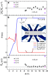
 measured on the ν=2 plateau at 1.4 K
(black), 2.2 K (magenta) and 4.2 K (violet).
(b) Longitudinal (Rxx) and Hall
(RH) resistances (a 100-nA current circulates between
I1 and I2 terminals, the longitudinal and Hall
voltages are measured using (V1, V2) and
(V2, V3) terminal-pairs, respectively.) for
B varying from −1 to 19 T for the graphene
sample (red and blue curves, respectively) and varying from 8 to
13 T for the GaAs sample (wine and grey curves, respectively).
 is the LL filling factor
calculated from the carrier density n0 determined at low
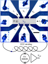
magnetic fields. Inset: optical image of the sample with terminal labels,
scale bar=100 μm. A very wide Hall resistance
plateau is observed in the large Hall bar device. (c) Accurate
measurements of the longitudinal resistance
  versus B at 1.4 K (black),
2.2 K (magenta) and 4.2 K (violet). Error bars
represent combined standard uncertainties, given with a coverage factor
k=1 corresponding to 1 s.d. A perfect quantization of
the Hall resistance, without significant deviations with regards to the
relative standard measurement uncertainty of 10−9,
is observed over a magnetic field range of 9 T from
10 T. It coincides with
  values lower than (30±20) μΩ.


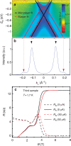
 direction in reciprocal space.
The momentum reference is at the
  point. The photon energy was 36 eV. The light was p polarized.
The black and red solid lines are fits for monolayer and bilayer graphene,
respectively. (b) ARPES intensity taken at
Eb=−1.2 eV, along
k⊥, evidences the small bilayer contribution
at
k⊥=±0.19 Å−1.
These ARPES measurements show that a graphene monolayer covers the whole SiC
surface, but ∼10% is covered by a second graphene layer.
(c) Longitudinal (Rxx, in dashed lines) and
transversal (RH, in solid lines) resistances as a function
of B for another Hall bar sample (400 μm by
1,200 μm) fabricated from another piece (5 ×
5 mm2 size) of the same graphene wafer as the
first sample (same graphene growth run). The carriers density of the sample
is ns=3.3 ×
1011 cm−2 and the
carrier mobility is
μ=3,300 cm2 V−1 s−1.
The observation of similar QHE and the measurement of similar electronic
properties in the first and third samples demonstrated the large-scale
homogeneity of the graphene growth and the repeatability of the fabrication
process of samples having a few
1011-cm−2 n-doping.
References
-
- Klitzing K. V., Dorda G. & Pepper M. New method for high-accuracy determination of the fine-structure constant based on quantized Hall resistance. Phys. Rev. Lett. 45, 494–497 (1980).
-
- Schopfer F. & Poirier W. Quantum resistance standard accuracy close to the zero-dissipation state. J. Appl. Phys. 114, 064508 (2013).
-
- Poirier W., Bounouh A., Piquemal F. & André J. P. A new generation of QHARS: discussion about the technical criteria for quantization. Metrologia 41, 285–294 (2004).
-
- Ahlers F.-J., Jeannneret B., Overney F., Schurr J. & Wood B. M. Compendium for precise ac measurements of the quantum Hall resistance. Metrologia 46, R1–R11 (2009).
-
- Poirier W. & Schopfer F. Resistance metrology based on the quantum Hall effect. Eur. Phys. J. Spec. Top. 172, 207–245 (2009).
Publication types
LinkOut - more resources
Full Text Sources
Other Literature Sources

