. 2015 Apr 21:5:9854.
doi: 10.1038/srep09854.

Cell voltage versus electrode potential range in aqueous supercapacitors

Affiliations

Cell voltage versus electrode potential range in aqueous supercapacitors

Zengxin Dai et al. Sci Rep. .

Abstract

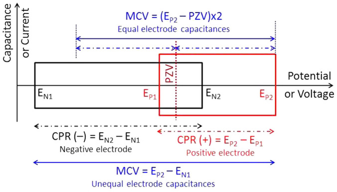
Supercapacitors with aqueous electrolytes and nanostructured composite electrodes are attractive because of their high charging-discharging speed, long cycle life, low environmental impact and wide commercial affordability. However, the energy capacity of aqueous supercapacitors is limited by the electrochemical window of water. In this paper, a recently reported engineering strategy is further developed and demonstrated to correlate the maximum charging voltage of a supercapacitor with the capacitive potential ranges and the capacitance ratio of the two electrodes. Beyond the maximum charging voltage, a supercapacitor may still operate, but at the expense of a reduced cycle life. In addition, it is shown that the supercapacitor performance is strongly affected by the initial and zero charge potentials of the electrodes. Further, the differences are highlighted and elaborated between freshly prepared, aged under open circuit conditions, and cycled electrodes of composites of conducting polymers and carbon nanotubes. The first voltammetric charging-discharging cycle has an electrode conditioning effect to change the electrodes from their initial potentials to the potential of zero voltage, and reduce the irreversibility.


Conflict of interest statement

The authors declare no competing financial interests.

Figures

Figure 1
Figure 1. A model of supercapacitor voltage.
Schematic illustration of supercapacitor maximum charging voltage (MCV), potential of zero voltage (PZV), and electrode capacitive potential range (CPR: EN2 − EN1 or EP2 − EP1 for the negative or positive electrode, respectively).
Figure 2
Figure 2. Performances of individual electrodes.
Capacitance – electrode potential plots of PAN-CNT, PPY-CNT, PEDOT-CNT, activated carbon (CMPB: Cabot Monarch Pigment Black 1300), MnO2-CNT and SnO2-CNT. Electrolyte: 0.5 mol L−1 KCl or 1 mol L−1 HCl as indicated. Reference electrode: Ag/AgCl in 3 mol L−1 KCl. The circular marks on some CVs indicate the stable open circuit potentials of the respective electrodes that were measured after immersion in the electrolyte for up to 4 hours.
Figure 3
Figure 3. Voltages of symmetrical supercapacitors.
Cyclic voltammograms of symmetrical supercapacitors with electrodes of electrodeposited (a,b) PAN-CNT in 1.0 mol L−1 HCl (deposition charge: 3.0 C, voltage scan rate: 5 mV s−1), (d) PPY-CNT (solid line, 2.8 C, 5 mV s−1) and PEDOT-CNT (dashed line, 3.0 C, 10 mV s−1) in 0.5 mol L−1 KCl. The PAN-CNT electrodes were fresh in (a) and aged under open circuit for 4 hours in (b). (c) Electrode potential of the positive electrode simultaneously recorded with the first cycle CV in (b). Insets in (a): Photographs of the PAN-CNT electrode (showing the electro-deposited PAN-CNT coating on a 6 mm diameter graphite disc) and the tube-cell supercapacitor.
Figure 4
Figure 4. Voltages of asymmetrical supercapacitors.
Cyclic voltammograms of asymmetrical supercapacitors of (a) 900 mC PAN-CNT (+) | 1.0 mol L−1 HCl | 2 mg CMPB (−), (b) 630 mC PPY-CNT (+) | 0.5 mol L−1 KCl | 1 mg CMPB (−), and (c) 3 C PEDOT-CNT (+) | 0.5 mol L−1 KCl | 1.7 mg CMPB (−). Voltage scan rates: (a) 10, (b) 20 and (c) 10 mV s−1, respectively.
Figure 5
Figure 5. Effect of operating voltage on charge-discharge cycle stability.
The 2nd and 500th cyclic voltammograms of PAN-CNT symmetrical supercapacitors with the maximum charging voltage (MCV) of (a) 0.65 V and (b) 0.68 V. Voltage scan rate: 10 mV s−1.
Figure 6
Figure 6. Effect of unequal electrode capacitances on maximum charging voltage.
Cyclic voltammograms of (a) chemically synthesised PPY-CNT (20 wt%) in two different potential windows, and (b) asymmetrical supercapacitors of (blue line) “5 mg PPY-CNT (+) | KCl | 10 mg AC (−)” at C+/C = 1.0, and (red line) “24 mg PPY-CNT (+) | KCl | 11 mg AC (−)” at C+/C = 3.0. Specific capacitance: 180 F g−1 for PPY−CNT and 125 F g−1 for activated carbon. Electrolyte: 3 mol L−1 KCl. Scan rate: 5 mV s−1.

References

    1. Simon P. & Gogotsi Y. Materials for electrochemical capacitors. Nat. Mater. 7, 845–854 (2008). - PubMed
    1. Chen G. Z. Understanding supercapacitors based on nano-hybrid materials with interfacial conjugation. Prog. Nat. Sci. Mater. Int. 23, 245–255 (2013).
    1. Amade R., Jover E., Caglar B., Mutlu T. & Bertran E. Optimization of MnO2/vertically aligned carbon nanotube composite for supercapacitor application. J. Power Sources 196, 5779–5783 (2011).
    1. Khomenko V., Raymundo-Piñero E., Frackowiak E. & Béguin F. High-voltage asymmetric supercapacitors operating in aqueous electrolyte. Appl. Phys. A 82, 567–573 (2006).
    1. Khomenko V., Raymundo-Piñero E. & Béguin F. Optimisation of an asymmetric manganese oxide/activated carbon. J. Power Sources 153, 183–190 (2006).

Publication types