

Peri-implant stress correlates with bone and cement morphology: Micro-FE modeling of implanted cadaveric glenoids
- PMID: 25929691
- PMCID: PMC4591115
- DOI: 10.1002/jor.22933
Peri-implant stress correlates with bone and cement morphology: Micro-FE modeling of implanted cadaveric glenoids
Abstract
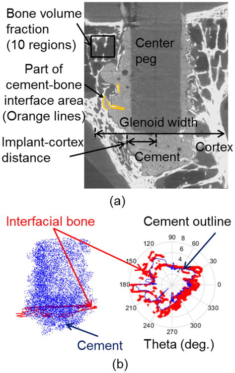
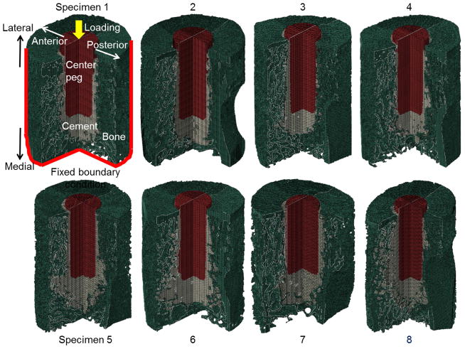
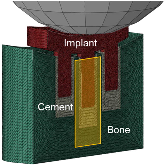
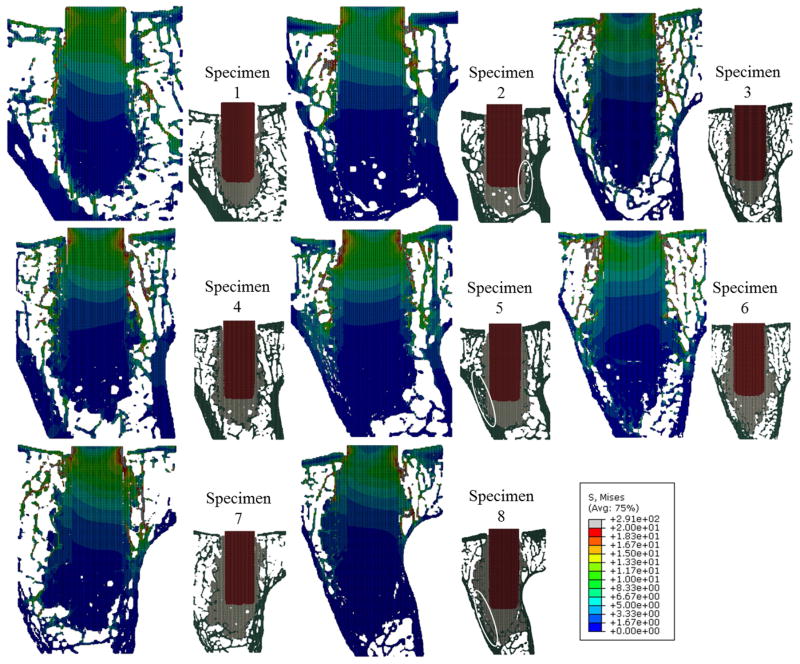
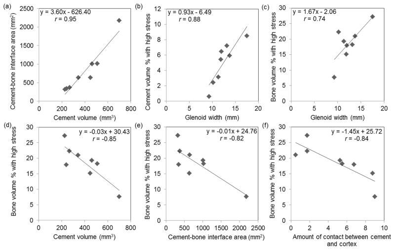
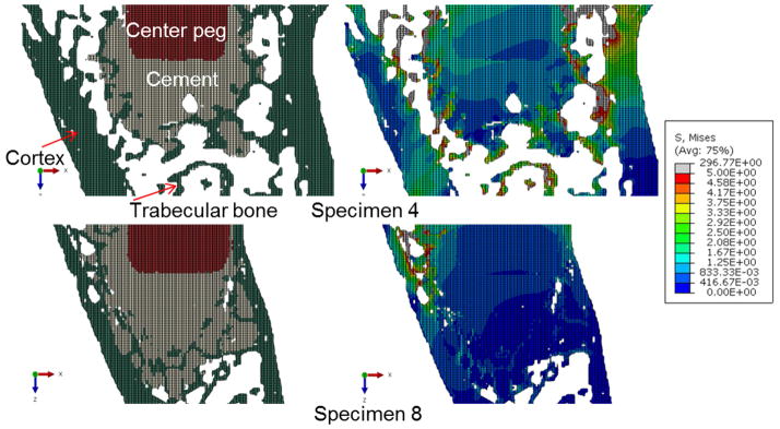
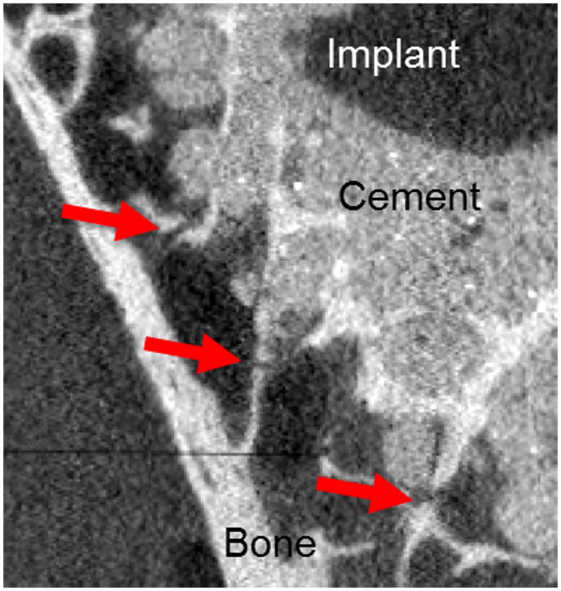
Aseptic loosening of cemented joint replacements is a complex biological and mechanical process, and remains a clinical concern especially in patients with poor bone quality. Utilizing high resolution finite element analysis of a series of implanted cadaver glenoids, the objective of this study was to quantify relationships between construct morphology and resulting mechanical stresses in cement and trabeculae. Eight glenoid cadavers were implanted with a cemented central peg implant. Specimens were imaged by micro-CT, and subject-specific finite element models were developed. Bone volume fraction, glenoid width, implant-cortex distance, cement volume, cement-cortex contact, and cement-bone interface area were measured. Axial loading was applied to the implant of each model and stress distributions were characterized. Correlation analysis was completed across all specimens for pairs of morphological and mechanical variables. The amount of trabecular bone with high stress was strongly negatively correlated with both cement volume and contact between the cement and cortex (r = -0.85 and -0.84, p < 0.05). Bone with high stress was also correlated with both glenoid width and implant-cortex distance. Contact between the cement and underlying cortex may dramatically reduce trabecular bone stresses surrounding the cement, and this contact depends on bone shape, cement amount, and implant positioning.
Keywords: cement morphology; finite element; glenoid implant; implant fixation.
© 2015 Orthopaedic Research Society. Published by Wiley Periodicals, Inc.
Figures
Similar articles
-
Cement stress predictions after anatomic total shoulder arthroplasty are correlated with preoperative glenoid bone quality.J Shoulder Elbow Surg. 2017 Sep;26(9):1644-1652. doi: 10.1016/j.jse.2017.02.023. Epub 2017 Apr 12. J Shoulder Elbow Surg. 2017. PMID: 28412104
-
The possibilities of uncemented glenoid component--a finite element study.Clin Biomech (Bristol). 2004 Mar;19(3):292-302. doi: 10.1016/j.clinbiomech.2003.12.002. Clin Biomech (Bristol). 2004. PMID: 15003345
-
Bone density and anisotropy affect periprosthetic cement and bone stresses after anatomical glenoid replacement: A micro finite element analysis.J Biomech. 2016 Jun 14;49(9):1724-1733. doi: 10.1016/j.jbiomech.2016.04.003. Epub 2016 Apr 8. J Biomech. 2016. PMID: 27087675
-
Computational analysis of primary implant stability in trabecular bone.J Biomech. 2015 Mar 18;48(5):807-15. doi: 10.1016/j.jbiomech.2014.12.008. Epub 2014 Dec 29. J Biomech. 2015. PMID: 25579993 Review.
-
Computational analyses of small endosseous implants in osteoporotic bone.Eur Cell Mater. 2010 Jul 21;20:58-71. doi: 10.22203/ecm.v020a06. Eur Cell Mater. 2010. PMID: 20665437 Review.
Cited by
-
Biomechanical effects of morphological variations of the cortical wall at the bone-cement interface.J Orthop Surg Res. 2016 Jul 1;11(1):72. doi: 10.1186/s13018-016-0405-y. J Orthop Surg Res. 2016. PMID: 27369636 Free PMC article.
-
Construct damage and loosening around glenoid implants: A longitudinal micro-CT study of five cadaver specimens.J Orthop Res. 2016 Jun;34(6):1053-60. doi: 10.1002/jor.23119. Epub 2015 Dec 28. J Orthop Res. 2016. PMID: 26630205 Free PMC article.
-
Surface coating of orthopedic implant to enhance the osseointegration and reduction of bacterial colonization: a review.Biomater Res. 2022 Jun 20;26(1):26. doi: 10.1186/s40824-022-00269-3. Biomater Res. 2022. PMID: 35725501 Free PMC article. Review.
-
Voxel-based micro-finite element analysis of dental implants in a human cadaveric mandible: Tissue modulus assignment and sensitivity analyses.J Mech Behav Biomed Mater. 2019 Jun;94:229-237. doi: 10.1016/j.jmbbm.2019.03.008. Epub 2019 Mar 13. J Mech Behav Biomed Mater. 2019. PMID: 30925312 Free PMC article.
References
-
- Amstutz HC, Ma SM, Jinnah RH, Mai L. Revision of aseptic loose total hip arthroplasties. Clin Orthop. 1982;170:21–33. - PubMed
-
- Clohisy JC, Calvert G, Tull F, et al. Reasons for Revision Hip Surgery: A Retrospective Review. Clin Orthop Relat Res Dec. 2004;2004 :188–192. - PubMed
-
- Insall JN, Dethmers DA. Revision of total knee arthroplasty. Clin Orthop. 1982;170:123–130. - PubMed
-
- Sharkey PF, Hozack WJ, Rothman RH, et al. Why are total knee arthroplasties failing today? Clin Orthop. 2002;404:7–13. - PubMed
Publication types
MeSH terms
Substances
Grants and funding
LinkOut - more resources
Full Text Sources
Other Literature Sources
