. 2015 Jul;36(7):1381-8.
doi: 10.3174/ajnr.A4302. Epub 2015 May 7.

Transmedullary Venous Anastomoses: Anatomy and Angiographic Visualization Using Flat Panel Catheter Angiotomography

Affiliations

Transmedullary Venous Anastomoses: Anatomy and Angiographic Visualization Using Flat Panel Catheter Angiotomography

L Gregg et al. AJNR Am J Neuroradiol. 2015 Jul.

Abstract

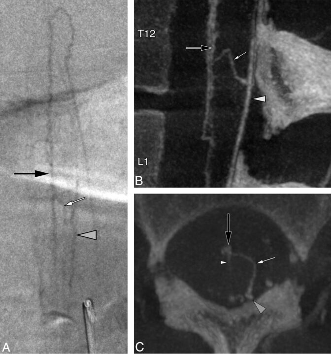
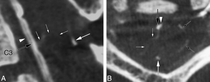
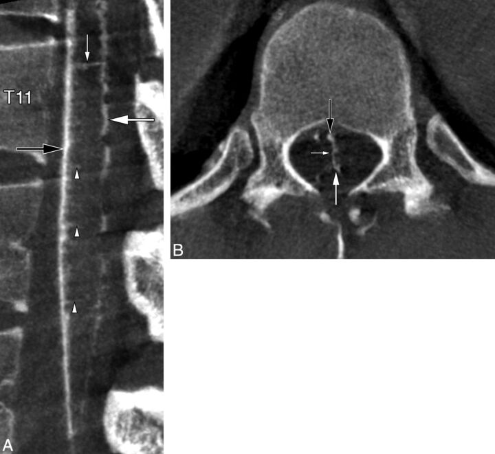
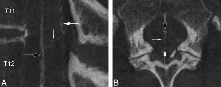
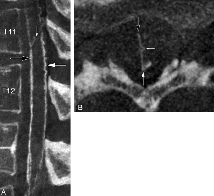
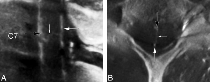
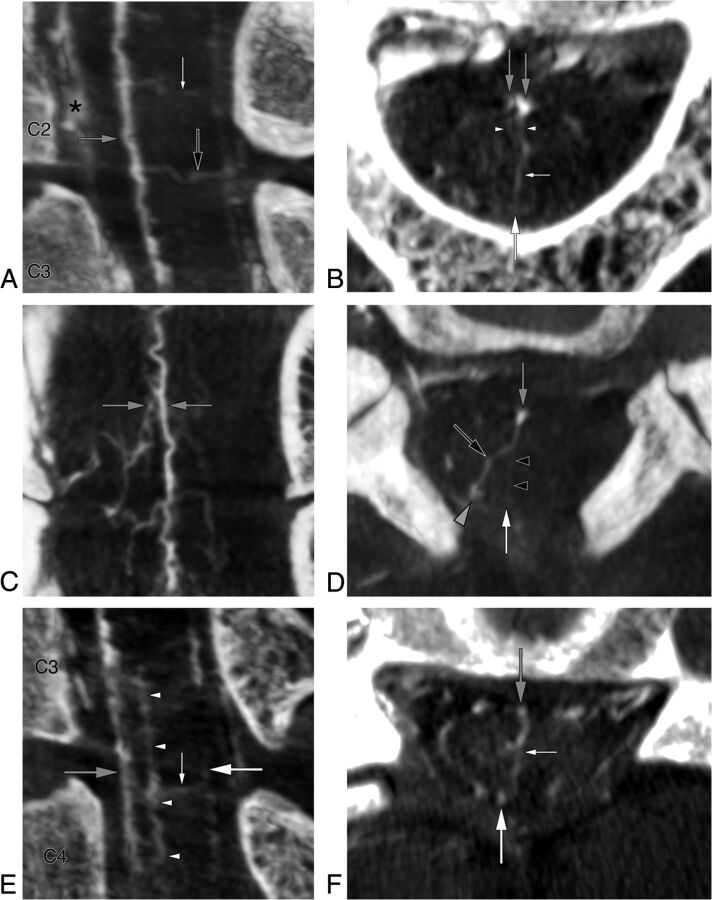
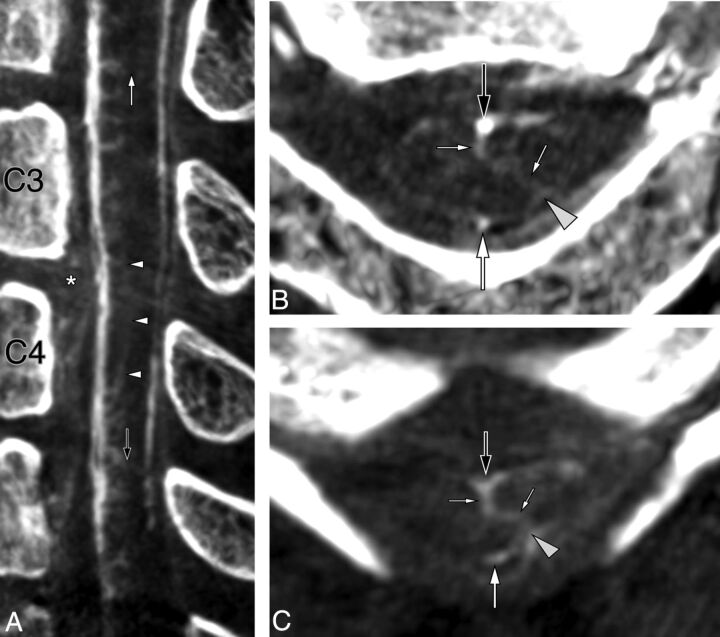
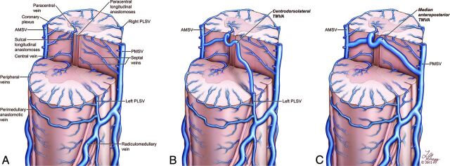
Flat panel catheter angiotomography, a recently developed angiographic technique, offers a spinal equivalent to the venous phase obtained during cerebral angiography. This report of 8 clinical cases discusses the flat panel catheter angiotomography appearance of a type of spinal venous structure until now principally known through the analysis of postmortem material, transmedullary venous anastomosis. The illustrated configurations include centrodorsolateral, median anteroposterior, median anteroposterior with duplicated origin, and combined centrodorsolateral/median anteroposterior transmedullary venous anastomoses, while a pathologic example documents the potential role of transmedullary venous anastomoses as collateral venous pathways. Two of the reported configurations have not been previously documented. Transmedullary venous anastomoses are normal venous structures that need to be differentiated from spinal cord anomalies, such as intramedullary vascular malformations.


Figures

Fig 1.
Fig 1.
A 36-year-old woman with a perimedullary anastomosis. A, Spinal DSA, left L1 injection, posteroanterior projection, late venous phase, shows an anastomotic connection (white arrow) between the AMSV (black arrow) and the left PLSV (gray arrowhead). The exact location of this anastomosis (intramedullary-versus-perimedullary) cannot be clearly established in this projection. A lateral projection would not offer additional information because the ventrodorsal course of both types of anastomoses would appear similar. B, FPCA, left L1 injection, sagittal MIP reconstruction (thickness = 8 mm). The morphology of the anastomosis (white arrow) and its points of connection with the AMSV (black arrow) and left PLSV (gray arrowhead) are better appreciated. C, FPCA, left L1 injection, axial MIP reconstruction (thickness = 8 mm). This axial view unequivocally establishes the superficial course of the perimedullary anastomosis (small arrow) over the lateral aspect of the spinal cord, between the AMSV (black arrow) and the left PLSV (gray arrowhead). A central vein is documented within the anteromedian fissure (white arrowhead).
Fig 2.
Fig 2.
A 51-year-old woman with a centrodorsolateral transmedullary venous anastomosis. A, FPCA, left vertebral artery injection, sagittal MIP reconstruction (thickness = 5 mm) shows a centrodorsolateral TMVA (small white arrows) connecting the AMSV (large black arrow) to the right PLSV. The PMSV (large white arrow) and anterior spinal artery (white arrowhead) are also documented. B, FPCA, left vertebral artery injection, axial MIP reconstruction (thickness = 5 mm) shows the path taken by the centrodorsolateral TMVA (small white arrows) between the AMSV (large black arrow) and the right PLSV. The PMSV (larger white arrow) and segments of the coronary plexus (small black arrows) are seen as well.
Fig 3.
Fig 3.
A 23-year-old woman with a median anteroposterior transmedullary venous anastomosis. A, FPCA, right T12 injection, sagittal MIP reconstruction (thickness = 3 mm). The median anteroposterior TMVA (small white arrow) extends between the AMSV (black arrow) and the PMSV (large white arrow) at the T11 level. Several central veins (arrowheads) are seen. B, FPCA, right T12 injection, axial MIP reconstruction (thickness = 3 mm), confirms the transmedullary course of the median anteroposterior TMVA (small white arrow) between the AMSV (black arrow) and the PMSV (large white arrow).
Fig 4.
Fig 4.
A 60-year-old woman with a median anteroposterior transmedullary venous anastomosis. A, FPCA, left L1 injection, sagittal MIP reconstruction (thickness = 3 mm), shows a median anteroposterior TMVA (small white arrow) coursing superiorly and posteriorly between the AMSV (black arrow) and the PMSV (large white arrow). B, FPCA, left L1 injection, axial MIP reconstruction (thickness = 10 mm). The median anteroposterior TMVA (small white arrow) extends from the AMSV (black arrow) to the PMSV (large white arrow). Note the typical lateral loop of the TMVA around the central canal at the level of the small white arrow.
Fig 5.
Fig 5.
A 74-year-old man with a median anteroposterior transmedullary venous anastomosis. A, FPCA, left L1 injection, sagittal MIP reconstruction (thickness = 3 mm), shows a median anteroposterior TMVA (small white arrow) extending between the AMSV (black arrow) and the PMSV (large white arrow). B, FPCA, left L1 injection, axial MIP reconstruction (thickness = 10 mm). The median anteroposterior TMVA (small white arrow) courses from the AMSV (black arrow) to the PMSV (large white arrow), showing a typical deviation around the central canal.
Fig 6.
Fig 6.
A 40-year-old woman with a median anteroposterior transmedullary venous anastomosis. A, FPCA, left costocervical trunk injection, sagittal MIP reconstruction (thickness = 2 mm). A median anteroposterior TMVA (small white arrow) connects the AMSV (black arrow) to the PMSV (large white arrow). B, FPCA, left costocervical trunk injection, axial MIP reconstruction (thickness = 4 mm), confirms the intramedullary trajectory of the median anteroposterior TMVA (small white arrow) between the AMSV (black arrow) and the PMSV (large white arrow).
Fig 7.
Fig 7.
A 52-year-old man with 2 median anteroposterior transmedullary venous anastomoses and a combined centrodorsolateral and median anteroposterior TMVA. A, FPCA, right vertebral injection, sagittal MIP reconstruction (thickness = 5 mm), reveals 2 TMVAs: a median anteroposterior TMVA (small white arrow) with a dual origin (documented in Fig 7B) from the AMSV (gray arrow) at C2 and a TMVA with combined median anteroposterior and centrodorsolateral characteristics (black arrow) between C2 and C3. The anterior internal epidural venous plexus is well-appreciated (asterisk). B, FPCA, right vertebral injection, axial MIP reconstruction (thickness = 3 mm), shows the median anteroposterior TMVA (small white arrow) at the C2 level, with a dual origin (arrowheads) from the AMSV and the surrounding venous network (gray arrows). The PMSV (large white arrow) is seen as well. C, FPCA, right vertebral injection, coronal MIP reconstruction (thickness = 4 mm), documents the segment of the AMSV and surrounding venous network from which the TMVA with dual roots originates (gray arrows). D, FPCA, right vertebral injection, axial MIP reconstruction (thickness = 4 mm). The TMVA with combined median anteroposterior (black arrowheads) and centrodorsolateral (black arrow) characteristics connects the AMSV (gray arrow) to the PMSV dorsally (white arrow) and to the right PLSV dorsolaterally (gray arrowhead) between the C2 and C3 levels. E, FPCA, right vertebral injection, sagittal MIP reconstruction (thickness = 4 mm). A median anteroposterior TMVA (small white arrow) extends between the AMSV (gray arrow) and the PMSV (large white arrow). A sulcal longitudinal anastomosis (arrowheads) is seen within the depth of the anteromedian fissure between C3 and C4. F, FPCA, right vertebral injection, axial MIP reconstruction (thickness = 3 mm), shows the course of the median anteroposterior TMVA (small white arrow) between the AMSV (gray arrow) and the PMSV (large white arrow).
Fig 8.
Fig 8.
A 57-year-old woman with a sulcal longitudinal anastomosis and 2 centrodorsolateral transmedullary venous anastomoses. A, FPCA, left vertebral injection, sagittal MIP reconstruction (thickness = 5 mm), shows mass effect on the anterior aspect of the spinal cord by protruded disk material at C3–C4 (asterisk), with a dearth of central veins at the corresponding level. The central veins above and below the lesion are prominent. A sulcal longitudinal anastomosis (white arrowheads) appears to serve as a collateral venous pathway in the depth of the anteromedian fissure. Two centrodorsolateral TMVAs are noted, respectively located cranially (white arrow) and caudally (black arrow) to the compressed area. B, FPCA, left vertebral injection, axial MIP reconstruction (thickness = 3 mm), shows the C2–C3 centrodorsolateral TMVA (small white arrows) connecting the AMSV (large black arrow) to the left PLSV (gray arrowhead). The PMSV (large white arrow) is seen as well. C, FPCA, left vertebral injection, axial MIP reconstruction (thickness = 2 mm), documents a second centrodorsolateral TMVA (small white arrows) at C4–C5, extending between the AMSV (large black arrow) and left PLSV (gray arrowhead), which continues its course medially to connect with the PMSV (large white arrow).
Fig 9.
Fig 9.
Artistic representation of the normal anatomy of the spinal venous system, emphasizing the 2 classic types of transmedullary venous anastomoses. A, The central veins establish longitudinal connections within the central gray matter (paracentral longitudinal anastomosis) and in the depth of the anteromedian fissure (sulcal longitudinal anastomosis). B, A centrodorsolateral TMVA is formed by a central vein connecting to a paracentral vein and continuing as a long oblique venous channel joining the ipsilateral PLSV. C, A median anteroposterior TMVA is formed by a large connection established between a central vein and a septal vein, with a typical loop around the central canal. Copyright 2015 Lydia Gregg.
Fig 10.
Fig 10.
Illustration reproduced from Kadyi H. Über die Blutgefässe des Menschlichen Rückenmarkes. Lemberg: Gubryonowisz & Schmidt; 1889 (Fig 9, page 146) shows the first TMVA depiction known to the authors (ie, a sagittal view of a centrodorsolateral TMVA). The vein, designated as v, courses laterally and posteriorly from the midsagittal plane to a PLSV. The segment a connects to a central vein c after looping around the central canal.

Similar articles

Cited by

References

    1. Akpek S, Brunner T, Benndorf G, et al. . Three-dimensional imaging and cone beam volume CT in C-arm angiography with flat panel detector. Diagn Interv Radiol 2005;11:10–13 - PubMed
    1. Zellerhoff M, Scholz B, Ruehrnschopf EP, et al. . Low contrast 3D reconstruction from C-arm data. SPIE Proceedings 2005;5745:646–55
    1. Chen J, Ethiati T, Gailloud P. Flat panel catheter angiotomography of the spinal venous system: an enhanced venous phase for spinal digital subtraction angiography. AJNR Am J Neuroradiol 2012;33:1875–81 - PMC - PubMed
    1. Pearl MS, Chen JX, Gregg L, et al. . Angiographic detection and characterization of “cryptic venous anomalies” associated with spinal cord cavernous malformations using flat-panel catheter angiotomography. Neurosurgery 2012;71:125–32 - PubMed
    1. Aadland TD, Thielen KR, Kaufmann TJ, et al. . 3D C-arm conebeam CT angiography as an adjunct in the precise anatomic characterization of spinal dural arteriovenous fistulas. AJNR Am J Neuroradiol 2010;31:476–80 - PMC - PubMed

LinkOut - more resources