Review
. 2015;25(1-2):105-34.
doi: 10.1615/jlongtermeffmedimplants.2015011817.

Application of hydrogels in heart valve tissue engineering

Affiliations
Review

Application of hydrogels in heart valve tissue engineering

Xing Zhang et al. J Long Term Eff Med Implants. 2015.

Abstract

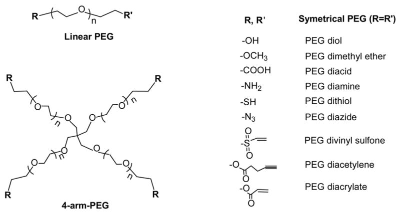
With an increasing number of patients requiring valve replacements, there is heightened interest in advancing heart valve tissue engineering (HVTE) to provide solutions to the many limitations of current surgical treatments. A variety of materials have been developed as scaffolds for HVTE including natural polymers, synthetic polymers, and decellularized valvular matrices. Among them, biocompatible hydrogels are generating growing interest. Natural hydrogels, such as collagen and fibrin, generally show good bioactivity but poor mechanical durability. Synthetic hydrogels, on the other hand, have tunable mechanical properties; however, appropriate cell-matrix interactions are difficult to obtain. Moreover, hydrogels can be used as cell carriers when the cellular component is seeded into the polymer meshes or decellularized valve scaffolds. In this review, we discuss current research strategies for HVTE with an emphasis on hydrogel applications. The physicochemical properties and fabrication methods of these hydrogels, as well as their mechanical properties and bioactivities are described. Performance of some hydrogels including in vitro evaluation using bioreactors and in vivo tests in different animal models are also discussed. For future HVTE, it will be compelling to examine how hydrogels can be constructed from composite materials to replicate mechanical properties and mimic biological functions of the native heart valve.


Figures

FIGURE 1
FIGURE 1
Examples of heart valve prostheses: (A) mechanical heart valve (Medtronic Open Pivot AP360®), (B) biological heart valve (Freestyle® Aortic Root Bioprosthesis), (C) living, fibrin-based tissue engineered tri-leaflet heart valve. Reproduced with permission from Flanagen et al.
FIGURE 2
FIGURE 2
(A) Movat’s pentachrome stain (collagen = yellow, PG/GAG = blue, elastin = black, cell nuclei = purple) of heart valve leaflets. The separate layers of the leaflet can be distinguished by the matrix stain in Movat’s: the fibrosa is mostly yellow from collagen; the spongiosa is blue with GAGs/PGs; and the ventricularis contains fine black elastic fibers. Reproduced with permission from Tseng et al. (B) Immunohistochemical staining of a section of aortic valve leaflet with CD31 (red), α-SMA (green) and DAPI (blue) to show the VECs line on the surfaces of the leaflet while VICs resident deep to the surfaces and through all layers. Scale bar = 200 μm.
FIGURE 3
FIGURE 3
VICs cultured (A) 2D on top of PEGylated collagen gel (0.15% w/v), (B) 3D in PEGylated collagen gel (0.15% w/v), and (C) 3D in PEG hydrogels (5% w/v), for 1 day. Cell density for 2D culture is ~104cells/cm2. Cell density for 3D culture is~106 cells/ml. Scale bar = 50 μm.
FIGURE 4
FIGURE 4
This valve mold consists of vascular and ventricular stamps machined from polyoxymethylene (POM), which are positioned against each other in a customized housing (also POM), consisting of two wall components, a lid and a base. The inner surface of the mold housing consists of a silicone cylinder. A polyvinylidene fluoride (PVDF) support mesh is sutured to each end of the silicone cylinder in order to prevent longitudinal compaction of the molded fibrin gel conduit. Reproduced with permission from Flanagan et al.
FIGURE 5
FIGURE 5
Structures of the PEG family of molecules. Reproduced with permission from Zhu.
FIGURE 6
FIGURE 6
Schematic depicting the fabrication of trilayer quasilaminates with an A-B-A composition. Gel A is 12.5% 3.4 kDa PEGDA, gel B is 10% 6 kDa PEGDA. This fabrication technique can be used to generate scaffolds with different stiffnesses and cellularity in each layer. Reproduced with permission from Tseng et al.
FIGURE 7
FIGURE 7
Printing heterogeneous valve and scaled valve constructs. (a) Porcine aortic valve rendered model was (b) printed, where root was formed with 700 MW PEG-DA hydrogel and the leaflets were formed with 700/8000 MW PEG-DA hydrogels. Key features such as the coronary ostium and sinuses were present (c) Scaffolds were printed with 700 MW PEG-DA at different scale for fidelity analysis, where the inner diameters (ID) were 22, 17, and 12 mm. (d) Axisymmetric valve model was (e) printed with two blends of hydrogels (f) and at 22, 17, and 12 mm ID. Scale bar = 1 cm. Reproduced with permission from Hockaday et al.
FIGURE 8
FIGURE 8
Schematic illustration of microtransfer molding technique employed to produce microstructured PVA hydrogels (left) and illustration of internal organization and structure of PVA hydrogels on a macromolecular (right) and supramolecular (middle) levels. Reproduced with permission from Jensen et al.
FIGURE 9
FIGURE 9
Bioprinting of aortic valve conduit. (A) Aortic valve model reconstructed from micro-CT images. The root and leaflet regions were identified with intensity thresholds and rendered separately into 3D geometries into STL format (green color indicates valve root and red color indicates valve leaflets); (B, C) schematic illustration of the bioprinting process with dual cell types and dual syringes; (B) root region of first layer generated by hydrogel with SMC; (C) leaflet region of first layer generated by hydrogel with VIC; (D) fluorescent image of first printed two layers of aortic valve conduit; SMC for valve root were labeled by cell tracker green and VIC for valve leaflet were labeled by cell tracker red. (E) printed aortic valve conduit. Reproduced with permission from Duan et al.
FIGURE 10
FIGURE 10
(A, B) Example of a full scale, pulsatile bioreactor for heart valve culture. Top view diagram (A) and pictured operationally inside incubator (B). Different parts of the bioreactor are labeled (I) atrium; (II) ventricle with air/liquid diaphragm to provide pulsatile flow; (III) compliance chamber; (IV) variable resistor. Valve is located in test section between pressure sensors (a). Reproduced with permission from Hildebrand et al. (C) Diagram of cyclic stretching bioreactor for fibrin based tissue engineered heart valves. Syringe pump is cycled to pressurize chamber and stretch valve tissue. Peristaltic pump provides pulsatile media flow through valve. Reproduced with permission from Syedain & Tranquillo. (D) Diagram of stretch bioreactor used for studying response of VICs to cyclic tensile strain. Cyclic strain applied by moving platen up and down, causing hydrogel sample to be pulled in tension by silicone slabs. Reproduced with permission from Gould et al. 2012.

References

    1. Yacoub MH, Takkenberg JJ. Will heart valve tissue engineering change the world? Nat Clin Pract Cardiovasc Med. 2005;2(2):60–1. - PubMed
    1. Cannegieter SC, Rosendaal FR, Briët E. Thromboembolic and bleeding complications in patients with mechanical heart valve prostheses. Circulation. 1994;89(2):635–41. - PubMed
    1. Fann JI, Miller DC, Moore KA, Mitchell RS, Oyer PE, Stinson EB, Robbins RC, Reitz BA, Shumway NE. Twenty-year clinical experience with porcine bioprostheses. Ann Thorac Surg. 1996;62(5):1301–11. discussion 1311–2. - PubMed
    1. Schoen FJ, Levy RJ. Tissue heart valves: current challenges and future research perspectives. J Biomed Mater Res; Founder’s Award, 25th Annual Meeting of the Society for Biomaterials, perspectives; Providence, RI. April 28-May 2, 1999; 1999. pp. 439–65. - PubMed
    1. Siddiqui RF, Abraham JR, Butany J. Bioprosthetic heart valves: modes of failure. Histopathology. 2009;55(2):135–44. - PubMed

Publication types