. 2015 May 30;6(15):13019-35.
doi: 10.18632/oncotarget.3864.

Molecular mechanisms of human IRE1 activation through dimerization and ligand binding

Affiliations

Molecular mechanisms of human IRE1 activation through dimerization and ligand binding

Amar Joshi et al. Oncotarget. .

Abstract

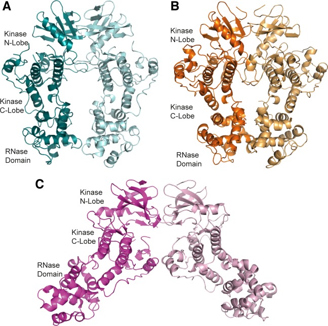
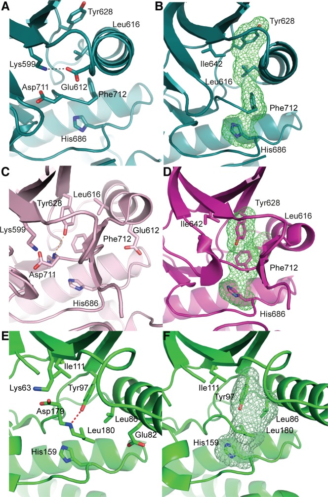
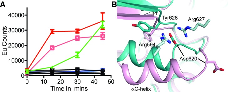
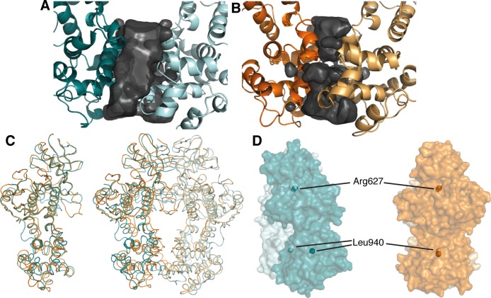
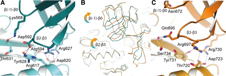
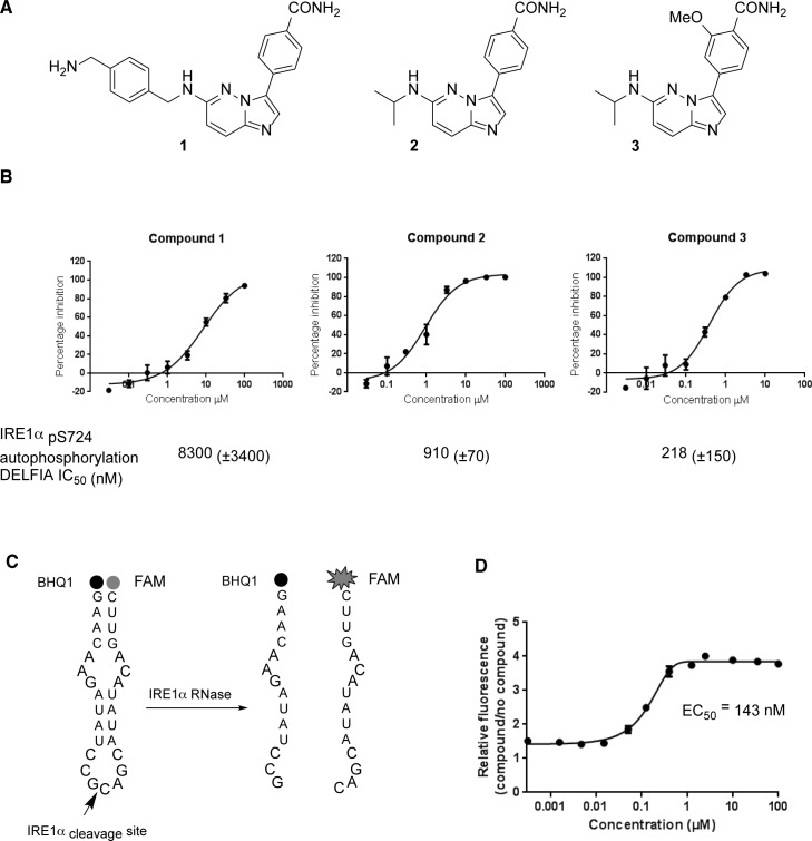
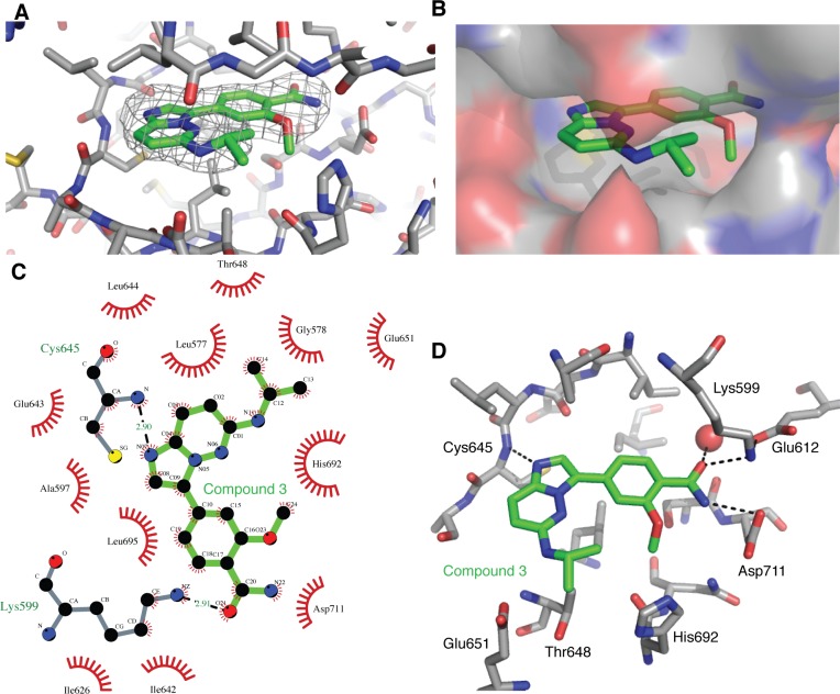
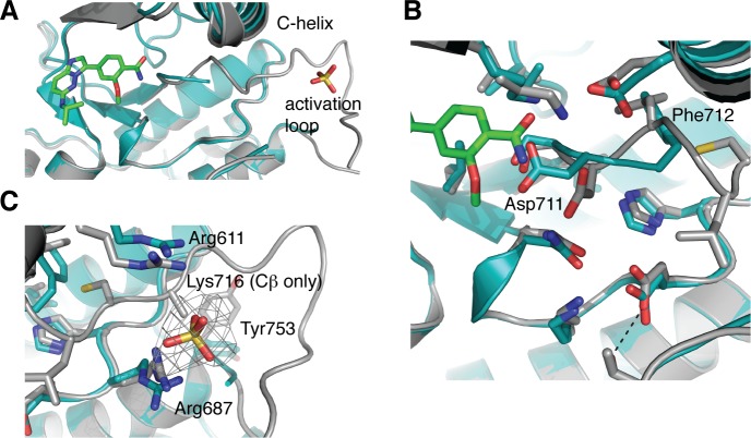
IRE1 transduces the unfolded protein response by splicing XBP1 through its C-terminal cytoplasmic kinase-RNase region. IRE1 autophosphorylation is coupled to RNase activity through formation of a back-to-back dimer, although the conservation of the underlying molecular mechanism is not clear from existing structures. We have crystallized human IRE1 in a back-to-back conformation only previously seen for the yeast homologue. In our structure the kinase domain appears primed for catalysis but the RNase domains are disengaged. Structure-function analysis reveals that IRE1 is autoinhibited through a Tyr-down mechanism related to that found in the unrelated Ser/Thr protein kinase Nek7. We have developed a compound that potently inhibits human IRE1 kinase activity while stimulating XBP1 splicing. A crystal structure of the inhibitor bound to IRE1 shows an increased ordering of the kinase activation loop. The structures of hIRE in apo and ligand-bound forms are consistent with a previously proposed model of IRE1 regulation in which formation of a back-to-back dimer coupled to adoption of a kinase-active conformation drive RNase activation. The structures provide opportunities for structure-guided design of IRE1 inhibitors.

Keywords: RNase; UPR; drug discovery; kinase.


Conflict of interest statement

CONFLICTS OF INTEREST

Please note that all authors who are, or have been, employed by The Institute of Cancer Research are subject to a “Rewards to Inventors Scheme” which may reward contributors to a programme that is subsequently licensed. The Institute of Cancer research has a commercial interest in the development of inhibitors of IRE1.

Figures

Figure 1
Figure 1. apo-hIRE1 forms a back-to-back dimer
A. The back-to-back dimer conformation of apo-hIRE. Cartoon representation of the two chains of apo-hIRE1 in the crystal structure colored teal and pale blue respectively. B. Cartoon representation of the active phosphorylated yIRE1 dimer in a back-to-back orientation (PDB ID 3FBV) [18], individual chains are shown in light and dark orange. C. Cartoon representation of ADP-hIRE1 (PDB ID 3P23) [22], individual chains are shown in magenta and pink.
Figure 2
Figure 2. apo-hIRE1 is in a kinase pre-active conformation, whereas ADP-hIRE1 is in an autoinhibited conformation
A. The kinase active site of apo-hIRE1. Main chain atoms shown in cartoon representation with selected side chain atoms shown. Atoms are colored by element: carbon, teal; oxygen, red; nitrogen, blue. The salt bridge between Lys599 and Glu612 is shown as a dashed black line. B. Aligned hydrophobic R-spine residues in the apo-hIRE1 N-lobe. The surface formed by the side chains of R-spine residues is shown as a green mesh. C. The kinase active site of ADP-hIRE1 crystal structure (PDB ID 3P23 [22]), shown in the equivalent view to A. Carbon atoms are colored pink. The hydrogen bonds between Tyr628 on β4 and Asp711 in the DFG motif is shown as a dashed orange lines. D. Non-aligned hydrophobic R-spine residues in the ADP-hIRE1 N-lobe, shown in the view equivalent to B. The surface formed by the side chains of R-spine residues is shown as a green mesh. E. The kinase active site of Nek7 is shown in cartoon representation with selected side chain and main chain atoms shown (equivalent view to A). The hydrogen bond between the Tyr97 side chain hydroxyl and Leu180 main chain amide is shown as a dashed red line. Main chain atoms are shown in cartoon representation. F. The active site of Nek7 (PDB ID 2WQM) [27] is in an autoinhibitory conformation. The surface formed by the side chains of R-spine residues is shown as a green mesh.
Figure 3
Figure 3. The αC-helix in the ADP-hIRE1 structure is incompatible with back-to-back dimer formation
Cartoon representation of the apo-hIRE1 structure (grey), with a semitransparent grey surface shown for one monomer. Cartoon representation of a monomer from the ADP-IRE1 structure [22]. Carbon atoms are colored by RMSD from the alignment to the apo-IRE1 monomer (from blue – low to red – high), while oxygen atoms are colored red and nitrogen atoms colored blue. For selected residues a black line is drawn between Cα atoms from identical residues between the apo- and ADP-hIRE1 crystal structures.
Figure 4
Figure 4. Mutation of hIRE1 Y628 enhances autophosphorylation
A. Autophosphorylation of hIRE1 wild-type (wt) and Y628 mutants measured by DELFIA assay. Results are color-coded by protein variant, protein concentration and presence or absence of ATP at 100 μM ATP. Black lines - absence of ATP. Green - wt IRE1 at 700 nM. Dark and light red – IRE1 Tyr628Phe at 1400 nM and 700 nM, respectively. Dark blue and light blue – Tyr628Leu at 1400 nM and 700 nM, respectively. B. View of the conformational changes between the ADP-hIRE1 structure (pink carbon atoms) and the apo-hIRE1 structure in the vicinity of Tyr628. Note that Asp620 in the αC-β4 linker moves by ~8 Å upon back-to-back dimer formation, and forms salt-bridge interactions with Arg594 and Arg627 from a second molecule of hIRE1 in the back-to-back dimer interface.
Figure 5
Figure 5. The apo-hIRE1 dimer is twisted compared to the phos-yIRE1 dimer, and the RNase domains are further apart
A. & B. Voids at the IRE1 RNase dimer interface are shown as a black surface. Structures are shown in cartoon representation and individual chains are colored different intensities; A. apo-hIRE1; B. phos-yIRE1. Voids generated by HOLLOW v1.2 [42]. C. Cα traces showing superposition of apo-hIRE1 (blue) and phos-yIRE1 (orange) structures. Left, Aligned over a single monomer there is good correspondence of secondary structure elements (overall 1.17 Å Cα RMSD). Right, Aligned over the dimer the correspondence of secondary structure elements is less good, especially in the RNase domain (overall 3.79 Å Cα RMSD). D. Side view of the apo-hIRE1 and phos-yIRE1 (PDB ID 3FBV) dimers [18], colored as in A & B. Specific conserved residues are indicated by spheres; Arg617 in the N-lobe interface and Leu940 within the RNase domain (hIRE1 numbering). Additional views are shown in Figure S2.
Figure 6
Figure 6. Differences in the back-to-back dimer contacts between hIRE1 and yIRE1
A. Apo-hIRE1 N-lobe dimer interface shown in cartoon representation with selected side chain and main chain atoms shown. Salt bridges and hydrogen bonds are shown as dashed black lines. Atoms are colored by element/chain: carbon, teal/pale blue; oxygen, red; nitrogen, blue. B. Ribbon representation of apo-hIRE1 and phos-yIRE1. The dimers are aligned over one chain – bottom left of panel. Perturbations in secondary structure of the opposing monomer can be seen. C. Phos-yIRE1 N-lobe dimer interface shown in the same representation as A (PDB ID 3FBV) [18]. Carbons in respective chains are colored light and dark orange.
Figure 7
Figure 7. Chemical synthesis and biological activity of a human IRE1 kinase inhibitor that stimulates RNase activity
A. Chemical structures of compounds 1, 2 and 3. B. Compounds 1, 2 and 3 inhibit the in vitro autophosphorylation of hIRE1α; representative curves shown, IC50 (±SD), n > 3 determinations. C. A 29-mer stem-loop RNA is cleaved specifically by hIRE1α in a FRET assay format to measure inhibition or activation of hIRE1α RNase function [29]. D. Kinase inhibitor 3 enhances hIRE1α RNase cleavage of the stem-loop RNA substrate in vitro.
Figure 8
Figure 8. Binding of compound 3 to the IRE1 kinase active site
A. Compound 3 (green carbon atoms) is located in the hIRE1 ATP binding pocket (grey carbon atoms). Wire mesh shows simulated annealing omit electron density map after removal of ligand from final model. B. Same view as A, but with hiRE1 shown as a translucent surface. C. Summary of the interactions generated using Ligplot+ [43]. Red flashes show Van der Waal contacts, H-bonds are marked with black dashed lines and distances in Å. D. Key protein-ligand interactions in the crystal structure. Black dashed lines are potential H-bonds. Red sphere is an ordered water molecule that mediates interactions between the ligand amide group and the protein DFG motif.
Figure 9
Figure 9. hIRE1 in complex with compound 3 has a more ordered activation loop
A. Superposition of apo-hIRE (teal) and ligand-bound hIRE1 (grey). Compound 3 and a sulfate ion are shown as sticks. The activation loop of apo-hIRE1 is mostly disordered. B. Magnified view in the vicinity of the DFG motif. In the presence of ligands, Asp711 and Phe712 adopt the positions found in active kinase structures. C. Magnified view in the vicinity of the sulfate ion. The wire mesh shows simulated annealing omit electron density map after removal of sulfate from final model. All structure figures were generated in PyMOL [44].
Figure 10
Figure 10. Graphical summary of IRE1 structures
A. hIRE1 crystallizes as a monomer in the complex with a sulfonamide inhibitor (PDB code 4U6R). The R-spine is disrupted by a chlorophenyl group that pushes the αC-helix out of position. B. ADP-hIRE1 crystallizes as a face-to-face dimer (PDB code 3P23). The monomers are in a conformation in which autophosphorylation is inhibited. The down position of Tyr628 breaks the R-spine, and αC-helix is rotated away from the N-lobe to generate a surface that cannot form the back-to-back dimer. C. apo-hIRE1 crystallizes as a back-to-back dimer. Tyr628 is in the up position, the αC-helix is in an active position, but the R-spine is not fully formed. D. The structure of hIRE in complex with a kinase inhibitor that stimulates RNase activity (I) has a more ordered activation loop and a fully-formed R-spine. E. phospho-yIRE1 crystallizes as a back-to-back dimer in which the activation loop is fully ordered, and the R-spine is intact (PDB code 3FBV). Full RNase activity depends on multimerisation of yIRE1 protomers (not shown).

References

    1. Walter P., Ron D. The unfolded protein response: from stress pathway to homeostatic regulation. Science. 2011;334:1081–6. - PubMed
    1. Ron D., Walter P. Signal integration in the endoplasmic reticulum unfolded protein response. Nat Rev Mol Cell Biol. 2007;8:519–29. - PubMed
    1. Sidrauski C., Walter P. The transmembrane kinase Ire1p is a site-specific endonuclease that initiates mRNA splicing in the unfolded protein response. Cell. 1997;90:1031–9. - PubMed
    1. Cox J.S., Shamu C.E., Walter P. Transcriptional induction of genes encoding endoplasmic reticulum resident proteins requires a transmembrane protein kinase. Cell. 1993;73:1197–206. - PubMed
    1. Shamu C.E., Walter P. Oligomerization and phosphorylation of the Ire1p kinase during intracellular signaling from the endoplasmic reticulum to the nucleus. EMBO J. 1996;15:3028–39. - PMC - PubMed

Publication types

MeSH terms