

CEREC CAD/CAM Chairside System
- PMID: 25992260
- PMCID: PMC4402686
CEREC CAD/CAM Chairside System
Abstract
Purpose: The aim of this paper was to describe the CEREC 3 chairside system, providing the clinicians a detailed analysis of the whole digital workflow. Benefits and limitations of this technology compared with the conventional prosthetic work-flow were also highlighted and discussed.
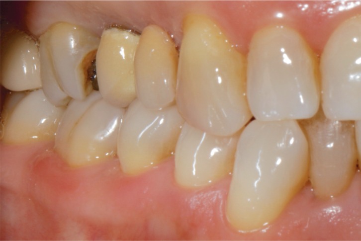
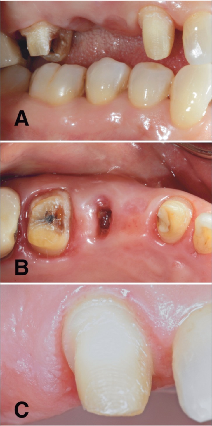
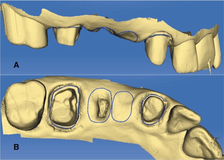
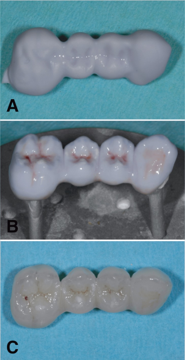
Materials and methods: Clinical procedures (tooth preparation, impression taking, adhesive luting), operational components and their capabilities as well as restorative materials used with CEREC 3 chairside system were reported.
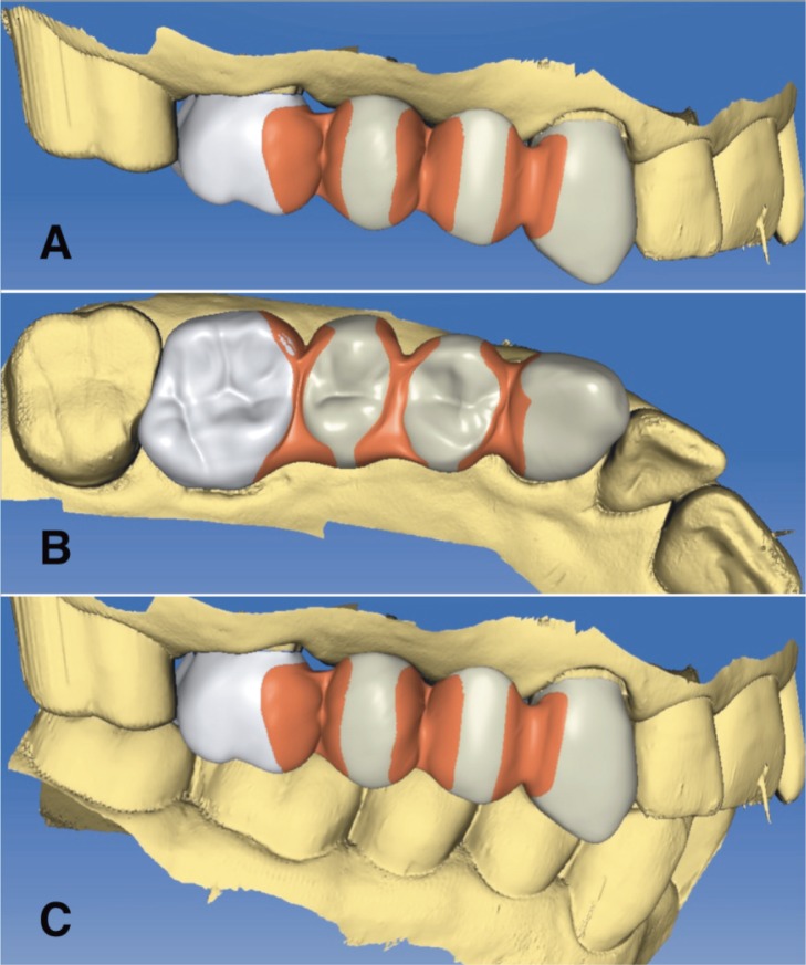
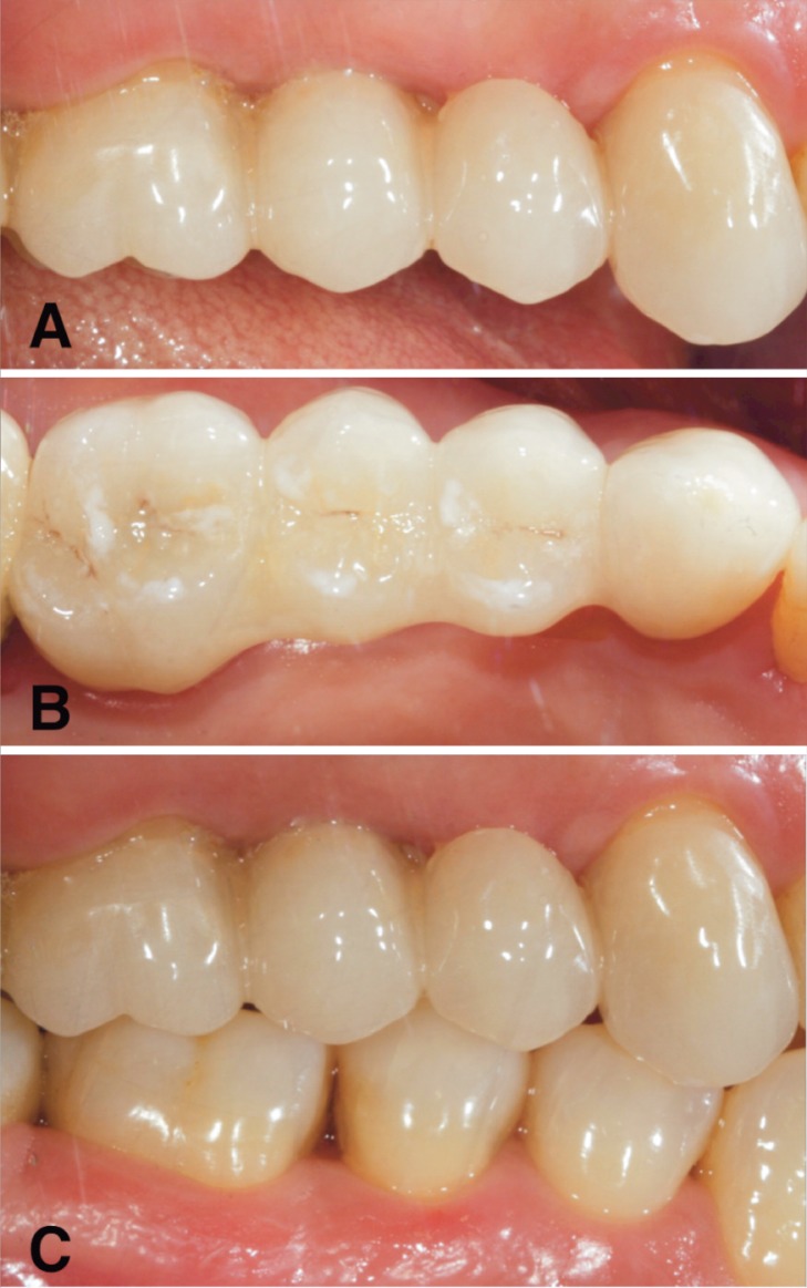
Results: The CEREC system has shown many positive aspects that make easier, faster and less expensive the prosthetic workflow. The operator-dependent errors are minimized compared to the conventional prosthetic protocol. Furthermore, a better acceptance level for the impression procedure has shown by the patients. The only drawback could be the subgingival placement of the margins compared with the supra/juxta gingival margins, since more time was required for the impression taking as well as the adhesive luting phase. The biocopy project seemed to be the best tool to obtain functionalized surfaces and keep unchanged gnathological data. Material selection was related to type of restoration.
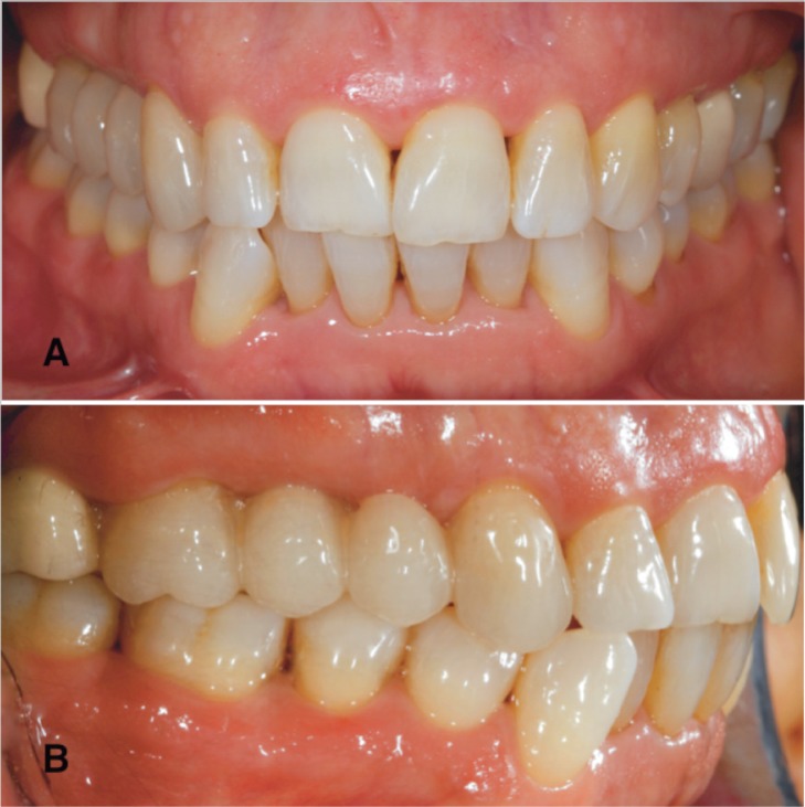
Conclusions: The evidence of our clinical practice suggests that CEREC 3 chairside system allows to produce highly aesthetic and reliable restorations in a single visit, while minimizing costs and patient discomfort during prosthetic treatment. However improvements in materials and technologies are needed in order to overcome the actual drawbacks.
Keywords: CAD/CAM; CEREC; adhesive luting; all-ceramic; chairside; metal-free; optical impression.
Figures
References
-
- Miyazaki T, Hotta Y, Kunii J, Kuriyama S, Tamaki Y. A review of dental CAD/CAM: current status and future perspectives from 20 years of experience. Dent Mater J. 2009;28(1):44–56. - PubMed
-
- Mörmann WH, Krejci I. Computer-designed inlays after 5 years in situ: clinical performance and scanning electron microscopic evaluation. Quintessence Int. 1992;23:109–15. - PubMed
-
- Mörmann WH. The origin of the Cerec method: a personal review of the first 5 years. Int J Comput Dent. 2004;7(1):11–24. - PubMed
-
- Mörmann WH. The evolution of the CEREC system. J Am Dent Assoc. 2006;137(Suppl):7S–13S. - PubMed
-
- Harsono M, Simon JF, Stein JM, Kugel G. Evolution of chairside CAD/CAM dentistry. Tex Dent J. 2013;130(3):238–44. - PubMed
LinkOut - more resources
Full Text Sources
Miscellaneous