

Reinforcement of Mono- and Bi-layer Poly(Ethylene Glycol) Hydrogels with a Fibrous Collagen Scaffold
- PMID: 26001970
- PMCID: PMC4618187
- DOI: 10.1007/s10439-015-1337-0
Reinforcement of Mono- and Bi-layer Poly(Ethylene Glycol) Hydrogels with a Fibrous Collagen Scaffold
Abstract
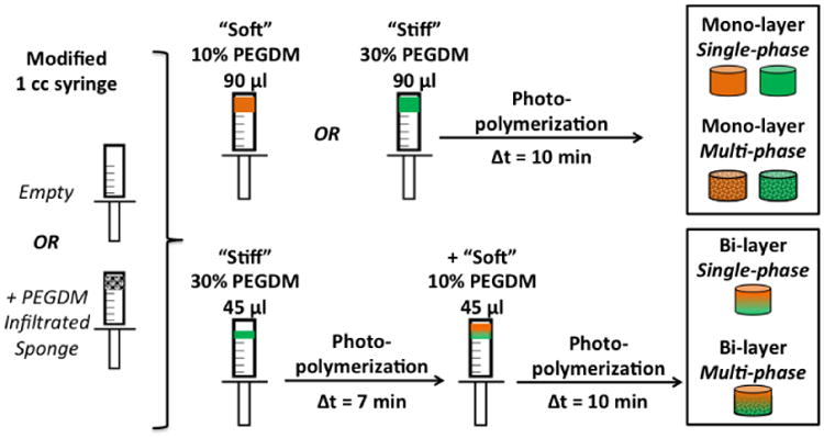
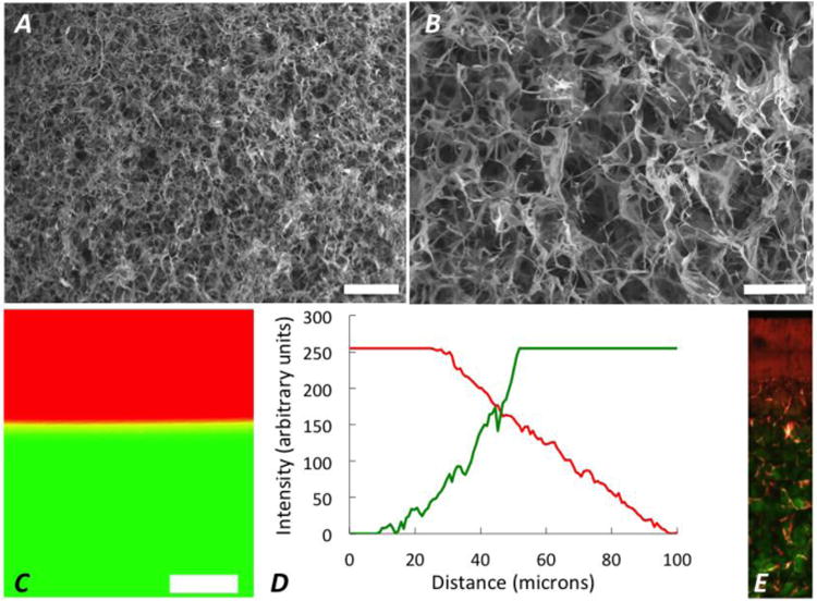
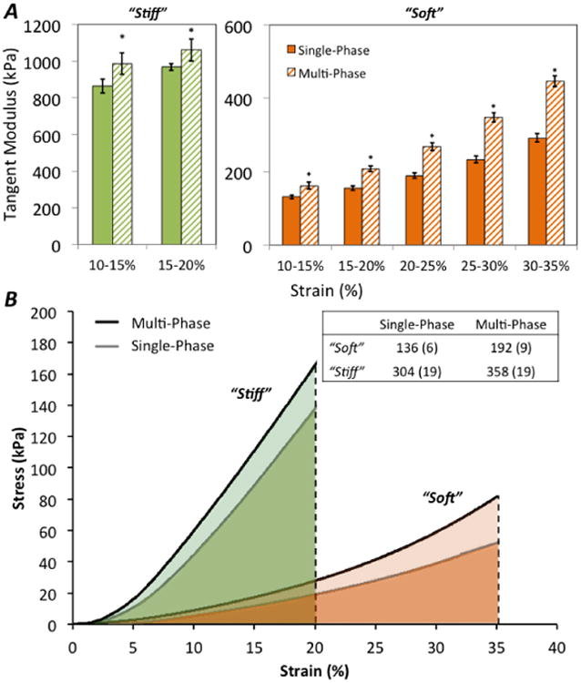
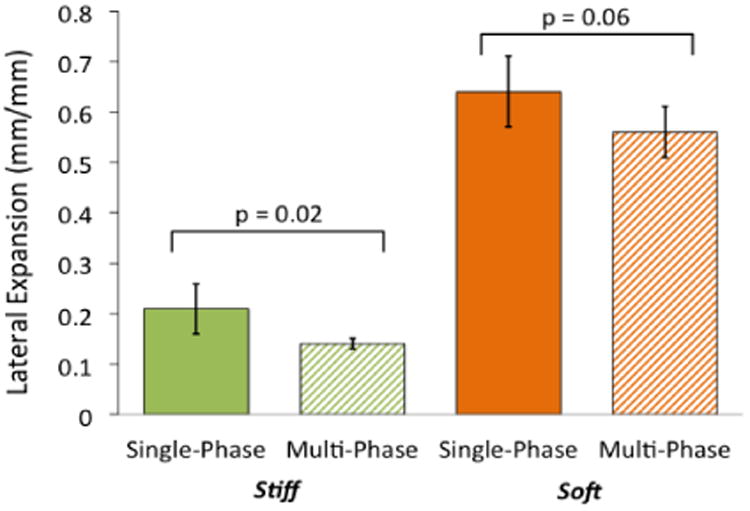
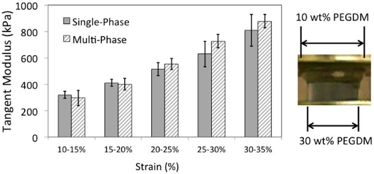
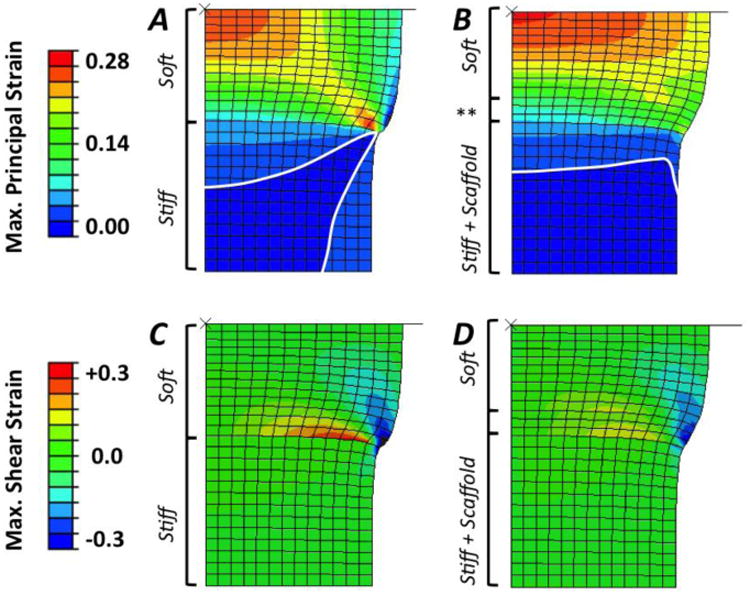
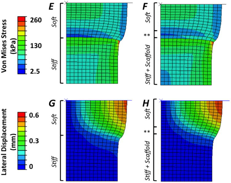
Biomaterial-based tissue engineering strategies hold great promise for osteochondral tissue repair. Yet significant challenges remain in joining highly dissimilar materials to achieve a biomimetic, mechanically robust design for repairing interfaces between soft tissue and bone. This study sought to improve interfacial properties and function in a bi-layer hydrogel interpenetrated with a fibrous collagen scaffold. 'Soft' 10% (w/w) and 'stiff' 30% (w/w) PEGDM was formed into mono- or bi-layer hydrogels possessing a sharp diffusional interface. Hydrogels were evaluated as single-(hydrogel only) or multi-phase (hydrogel + fibrous scaffold penetrating throughout the stiff layer and extending >500 μm into the soft layer). Including a fibrous scaffold into both soft and stiff mono-layer hydrogels significantly increased tangent modulus and toughness and decreased lateral expansion under compressive loading. Finite element simulations predicted substantially reduced stress and strain gradients across the soft-stiff hydrogel interface in multi-phase, bilayer hydrogels. When combining two low moduli constituent materials, composites theory poorly predicts the observed, large modulus increases. These results suggest material structure associated with the fibrous scaffold penetrating within the PEG hydrogel as the major contributor to improved properties and function-the hydrogel bore compressive loads and the 3D fibrous scaffold was loaded in tension thus resisting lateral expansion.
Keywords: Hydrogel; Interface; Mechanical properties; Multi-phase; Osteochondral; Scaffold; Tissue engineering.
Figures
Similar articles
-
An in situ forming collagen-PEG hydrogel for tissue regeneration.Acta Biomater. 2012 Jan;8(1):124-32. doi: 10.1016/j.actbio.2011.07.028. Epub 2011 Aug 26. Acta Biomater. 2012. PMID: 21911086
-
The effects of dynamic compressive loading on human mesenchymal stem cell osteogenesis in the stiff layer of a bilayer hydrogel.J Tissue Eng Regen Med. 2019 Jun;13(6):946-959. doi: 10.1002/term.2827. Epub 2019 May 7. J Tissue Eng Regen Med. 2019. PMID: 30793536 Free PMC article.
-
Mechanical characterization of sequentially layered photo-clickable thiol-ene hydrogels.J Mech Behav Biomed Mater. 2017 Jan;65:454-465. doi: 10.1016/j.jmbbm.2016.09.007. Epub 2016 Sep 8. J Mech Behav Biomed Mater. 2017. PMID: 27664813
-
Bioactive modification of poly(ethylene glycol) hydrogels for tissue engineering.Biomaterials. 2010 Jun;31(17):4639-56. doi: 10.1016/j.biomaterials.2010.02.044. Epub 2010 Mar 19. Biomaterials. 2010. PMID: 20303169 Free PMC article. Review.
-
A review on gradient hydrogel/fiber scaffolds for osteochondral regeneration.J Tissue Eng Regen Med. 2018 Apr;12(4):e1974-e1990. doi: 10.1002/term.2628. Epub 2018 Jan 28. J Tissue Eng Regen Med. 2018. PMID: 29243352 Review.
Cited by
-
Injectable scaffolds: Preparation and application in dental and craniofacial regeneration.Mater Sci Eng R Rep. 2017 Jan;111:1-26. doi: 10.1016/j.mser.2016.11.001. Mater Sci Eng R Rep. 2017. PMID: 28649171 Free PMC article.
-
A Stereolithography-Based 3D Printed Hybrid Scaffold for In Situ Cartilage Defect Repair.Macromol Biosci. 2018 Feb;18(2):10.1002/mabi.201700267. doi: 10.1002/mabi.201700267. Epub 2017 Dec 21. Macromol Biosci. 2018. PMID: 29266791 Free PMC article.
-
Physical Gold Nanoparticle-Decorated Polyethylene Glycol-Hydroxyapatite Composites Guide Osteogenesis and Angiogenesis of Mesenchymal Stem Cells.Biomedicines. 2021 Nov 6;9(11):1632. doi: 10.3390/biomedicines9111632. Biomedicines. 2021. PMID: 34829861 Free PMC article.
-
A Review on the Adaption of Alginate-Gelatin Hydrogels for 3D Cultures and Bioprinting.Materials (Basel). 2021 Feb 10;14(4):858. doi: 10.3390/ma14040858. Materials (Basel). 2021. PMID: 33579053 Free PMC article. Review.
-
3D Silk Fiber Construct Embedded Dual-Layer PEG Hydrogel for Articular Cartilage Repair - In vitro Assessment.Front Bioeng Biotechnol. 2021 Mar 24;9:653509. doi: 10.3389/fbioe.2021.653509. eCollection 2021. Front Bioeng Biotechnol. 2021. PMID: 33842448 Free PMC article.
References
-
- Bryant SJ, Bender RJ, Durand KL, Anseth KS. Encapsulating Chondrocytes in degrading PEG hydrogels with high modulus: Engineering gel structural changes to facilitate cartilaginous tissue production. Biotechnol Bioeng. 2004;86:747–755. - PubMed
-
- Bullough P, Goodfellow J. The significance of the fine structure of articular cartilage. J Bone Joint Surg Br. 1968;50:852–857. - PubMed
-
- Burdick JA, Anseth KS. Photoencapsulation of osteoblasts in injectable RGD-modified PEG hydrogels for bone tissue engineering. Biomaterials. 2002;23:4315–4323. - PubMed
Publication types
MeSH terms
Substances
Grants and funding
LinkOut - more resources
Full Text Sources
Other Literature Sources
