. 2015 Jun 23;54(24):3839-50.
doi: 10.1021/acs.biochem.5b00427. Epub 2015 Jun 10.

The Fifth Transmembrane Segment of Cystic Fibrosis Transmembrane Conductance Regulator Contributes to Its Anion Permeation Pathway

Affiliations

The Fifth Transmembrane Segment of Cystic Fibrosis Transmembrane Conductance Regulator Contributes to Its Anion Permeation Pathway

Jingyao Zhang et al. Biochemistry. .

Abstract

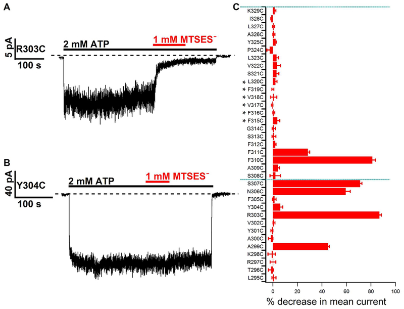
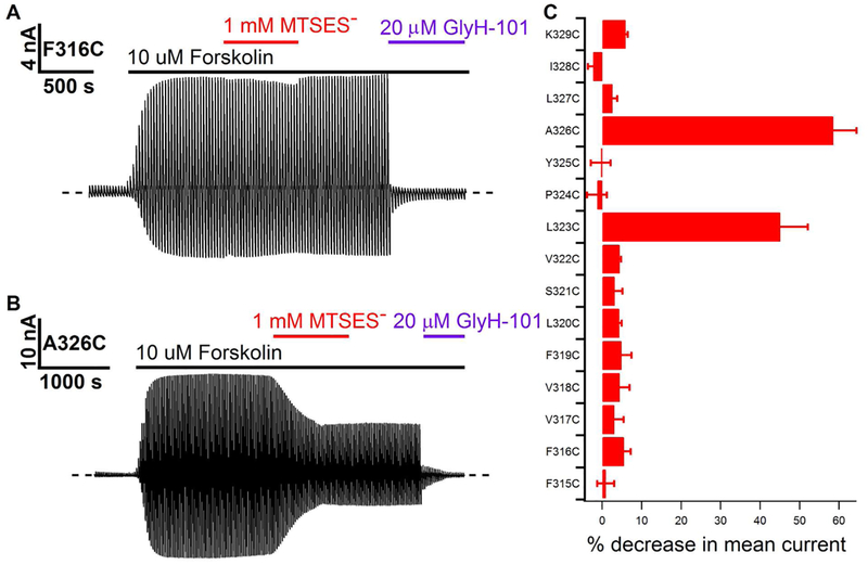
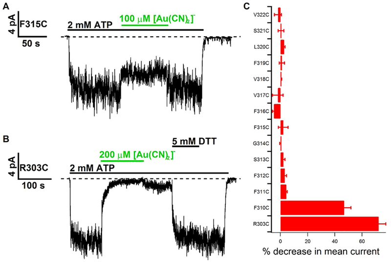
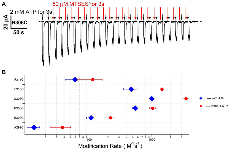
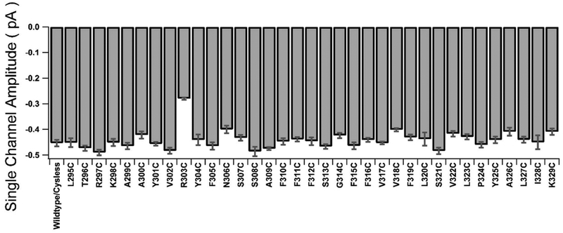
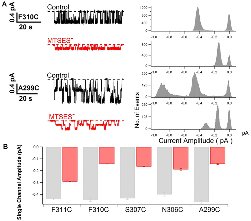
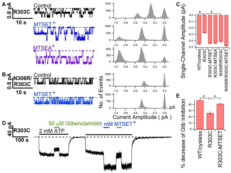
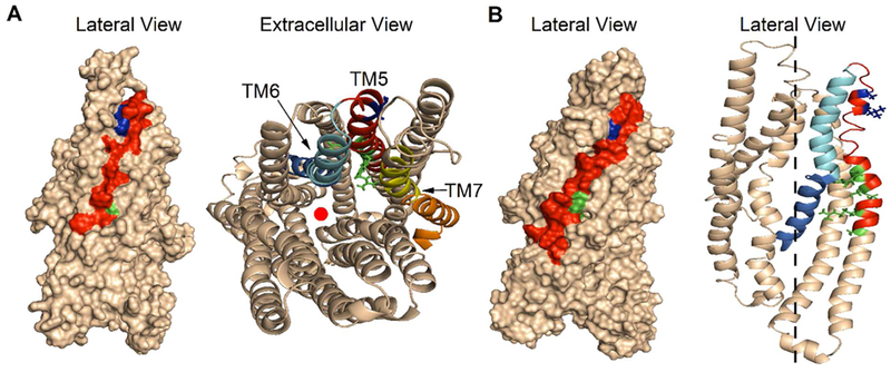
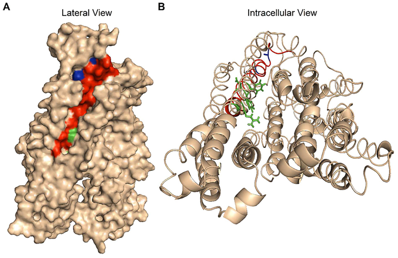
Previous studies have identified several transmembrane segments (TMs), including TM1, TM3, TM6, TM9, TM11, and TM12, as pore-lining segments in cystic fibrosis transmembrane conductance regulator (CFTR), but the role of TM5 in pore construction remains controversial. In this study, we employed substituted cysteine accessibility methodology (SCAM) to screen the entire TM5 defined by the original topology model and its cytoplasmic extension in a Cysless background. We found six positions (A299, R303, N306, S307, F310, and F311) where engineered cysteines react to intracellular 2-sulfonatoethyl methanethiosulfonate (MTSES⁻). Quantification of the modification rate of engineered cysteines in the presence or absence of ATP suggests that these six residues are accessible in both the open and closed states. Whole-cell experiments with external MTSES⁻ identified only two positive positions (L323 and A326), resulting in a segment containing 11 consecutive amino acids, where substituted cysteines respond to neither internal nor external MTSES⁻, a unique feature not seen previously in CFTR's pore-lining segments. The observation that these positions are inaccessible to channel-permeant thiol-specific reagent [Au(CN)₂]⁻ suggests that this segment of TM5 between F311 and L323 is concealed from the pore by other TMs and/or lipid bilayers. In addition, our data support the idea that the positively charged arginine at position 303 poses a pure electrostatic action in determining the single-channel current amplitude of CFTR and the effect of an open-channel blocker glibencalmide. Collectively, we conclude that the cytoplasmic portion of CFTR's TM5 lines the pore. Our functional data are remarkably consistent with predicted structural arrangements of TM5 in some homology models of CFTR.


Conflict of interest statement

The authors declare no competing financial interest.

Figures

Figure 1.
Figure 1.
Cysteine scanning of TM5 in CFTR with intracellularly applied MTSES. (A) Representative current trace recorded at −50 mV in an inside-out membrane patch containing R303C-CFTR channels. The dashed line represents the baseline. Application of a saturating concentration of ATP elicited chloride currents (downward deflections). The ATP-induced CFTR current was reduced by intracellular MTSES treatment. The decrease in current was not restored by the removal of MTSES, indicating that the decrease in current was likely due to a covalent modification of C303 by MTSES. (B) Representative recording of Y304C-CFTR channels using an experimental protocol similar to that described for panel A. The ATP-induced current was not altered upon intracellular MTSES treatment, suggesting that the cysteine placed at position 304 is not accessible to intracellular MTSES. (C) Summary of the percent decrease in macroscopic mean currents after intracellular application of MTSES for each cysteine-substituted channel (from cytoplasmic side L295C to extracellular side K329C). Asterisks mark the positions selected for SCAM studies by Wang et al. The dotted lines mark the membrane boundaries depicted in the originally defined CFTR topology. n = 3–9. Data points in this and all subsequent figures are presented as means ± SEM.
Figure 2.
Figure 2.
Cysteine scanning of CFTR TM5 with extracellularly applied MTSES in the whole-cell configuration. (A) Representative recording of whole-cell currents from F316C-CFTR channels. The dashed line represents the zero current level. A voltage ramp ranging from −100 to 100 mV was applied every 5 s. After the currents were fully activated by forskolin, 1 mM MTSES was applied extracellularly for several minutes until a steady state was reached. MTSES was subsequently washed out. The final baseline conductance was obtained with 20 μM CFTR blocker GlyH-101 to abolish all residual CFTR currents. (B) Representative recording of whole-cell patch currents of A326C-CFTR channels using a protocol similar to that described for panel A. The CFTR current induced by forskolin decreased upon the application of extracellular MTSES. (C) Summary of the percentage decrease in macroscopic mean currents after the extracellular application of MTSES for each cysteine-substituted channel (from cytoplasmic side F315C to extracellular side K329C). n = 3 or 4.
Figure 3.
Figure 3.
Effects of channel-permeant thiol-specific reagent [Au(CN)2] on cysteines introduced into TM5. (A) Continuous current trace recorded from an inside-out membrane patch containing F315C-CFTR channels. The dashed line represents the baseline current level. Application of a saturating concentration of ATP elicited chloride currents following activation of the channels by 32 IU/mL PKA and ATP (not shown). The ATP-induced current is decreased upon the addition of intracellular [Au(CN)2], but the current completely recovered after the removal of [Au(CN)2]. (B) Representative current recording of R303C-CFTR channels under an experimental protocol similar to that described for panel A. The current decrease upon intracellular [Au(CN)2] treatment was not restored upon the removal of [Au(CN)2]. However, the application of DTT restored all the current, indicating that the current decrease was due to covalent modification by [Au(CN)2]. (C) Summary of the percentage decrease in macroscopic mean currents after intracellular application of [Au(CN)2] for each cysteine-substituted channel (from cytoplasmic side F311C to extracellular side V322C together with F310C and R303C as positive controls). n = 3–5.
Figure 4.
Figure 4.
Quantitative assessments of modification rates by intracellular MTSES in the absence and presence of ATP. (A) Representative result showing how the modification rate for intracellular MTSES in the absence of ATP was estimated (see Experimental Procedures and Results for details). The dashed line represents the baseline current level. (B) Summary of MTSES modification rates in the absence and presence of ATP at all six positive positions. n = 3–9.
Figure 5.
Figure 5.
Summary of the single-channel current amplitude for WT/Cysless-CFTR and all cysteine-substituted channels. The transmembrane voltage was clamped at −50 mV. The data are shown as means ± SEM (n = 3–18). The only mutant that shows a dramatic difference in the single-channel current amplitude is R303C-CFTR.
Figure 6.
Figure 6.
Modification by MTSES reduces the single-channel current amplitude of each reactive mutant. (A) Single-channel recordings of F310C-and A299C-CFTR showing a significant decrease in the single-channel current amplitude after the treatment with MTSES. The dashed line represents the closed-state current level. All-point histograms of the corresponding current traces are presented to show the decrease in single-channel current amplitudes by MTSES. (B) Summary of changes in the single-channel current amplitude before (gray) and after MTSES modification (red) at five reactive positions (n = 3–18) (the single-channel current amplitude of R303C-CFTR after MTSES modification is too small to be quantified accurately).
Figure 7.
Figure 7.
Effects of charge replacement at position 303. (A) Single-channel recordings demonstrating an increase in the single-channel current amplitude of R303C-CFTR after modification by MTSET+ or MTSEA+. The corresponding all-point histogram is presented to the right of each current trace. (B) Restoration of the single-channel current amplitude for R303C-CFTR by introducing a positively charged residue at position 306 (i.e., control of N306R/R303C-CFTR), and a further increase in the single-channel current amplitude by MTSET+ modification. An all-point histogram for each single-channel trace is also presented. (C) Summary of the single-channel current amplitudes for R303C-CFTR and N306R/R303C-CFTR and those after modification by positively charged MTS reagents (n = 4–11). Asterisks mark statistically significant differences (p <0..05). (D) Representative macroscopic current recording showing an increase in glibenclamide block after MTSET+ modification on R303C-CFTR. The dashed line represents the closed-state current level. (E) Summary of glibenclamide block for WT/Cysless-CFTR, R303C-CFTR and MTSET+-modified R303C-CFTR. Glib refers to glibenclamide. Asterisks mark statistically significant differences (p < 0.05). n = 4–7.
Figure 8.
Figure 8.
Lateral view and extracellular views of two outward-facing structural models of CFTR’s TMDs, which represent the presumed open-channel conformation. The models were built on the basis of the crystal structure of a bacterial ABC transporter Sav1866. (A) Lateral view (left) with a surface representation and its extracellular view (right) with a ribbon representation of the modeled structure of Mornon et al. The NBD1-RD (residues 370–850) and NBD2-C terminal (residues 1156–1480) are not shown here. Two TMDs of CFTR were colored wheat. Of note, the lateral view shows that the major portion of red-colored TM5 is located at the periphery of the CFTR protein and hence away from the centrally located pore. Positive hits for intracellular MTSES are colored green, and two extracellular positive hits, L323 and A326, are colored blue. It is shown in the extracellular view that, while L323 and A326 are away from the pore axis (red solid circle), four of six of the intracellular positive hits (green) are pore-lining residues with their side chains exposed to the permeation pathway. F310 is buried in other TMs, and N306 is pointing to the lipid phase. Positions external to F312 are hidden behind the outer halves of TM6 (cyan) and TM7 (yellow). The cytoplasmic halves of TM6 (marine) and TM7 (orange) bent away from TM5 so that positions starting from F311 on TM5 are exposed to the pore. (B) Lateral view (left) of two TMDs of one outward-facing, “channel-like” CFTR homology model and its lateral view (right) of TMD1 with a ribbon representation developed by Dalton et al. TMD2 has been omitted to better view the relative positions of TM5 and other TMs. The dashed line represents the pore axis. Color codes for all residues are the same as in panel A. The observations from both views are similar to those in panel A despite a significant difference in the arrangement of TMs in these two structures.
Figure 9.
Figure 9.
Lateral and cytoplasmic views of an inward-facing structural model representing the presumed closed conformation of CFTR. This model in ref was based on the crystal structure of a bacterial ABC lipid flippase, MsbA. Color codes are the same as in Figure 8. (A) A lateral view with a surface representation shows that the majority of TM5 (red), including two extracellular positive hits, L323 and A326 (blue), is located at the periphery of the CFTR protein. (B) An intracellular view shows that all six positive hits with intracellular MTSES are located on one face of TM5 where the side chains are exposed to the aqueous environment of the inner vestibule, whereas positions external to F312 (red and blue) are hidden behind other TMs.

Similar articles

Cited by

References

    1. Dean M, and Annilo T (2005) Evolution of the ATP-binding cassette (ABC) transporter superfamily in vertebrates. Annu. Rev. Genomics Hum. Genet 6, 123–142. - PubMed
    1. Riordan JR, Rommens JM, Kerem B, Alon N, Rozmahel R, Grzelczak Z, Zielenski J, Lok S, Plavsic N, Chou JL, et al. (1989) Identification of the cystic fibrosis gene: Cloning and characterization of complementary DNA. Science 245, 1066–1073. - PubMed
    1. Bear CE, Li CH, Kartner N, Bridges RJ, Jensen TJ, Ramjeesingh M, and Riordan JR (1992) Purification and functional reconstitution of the cystic fibrosis transmembrane conductance regulator (CFTR). Cell 68, 809–818. - PubMed
    1. Moskowitz SM, Chmiel JF, Sternen DL, Cheng E, Gibson RL, Marshall SG, and Cutting GR (2008) Clinical practice and genetic counseling for cystic fibrosis and CFTR-related disorders. Genet. Med 10, 851–868. - PMC - PubMed
    1. Hwang TC, and Kirk KL (2013) The CFTR ion channel: Gating, regulation, and anion permeation. Cold Spring Harbor Perspect. Med 3, a009498. - PMC - PubMed

Publication types

MeSH terms

LinkOut - more resources