

doi: 10.1007/s10162-015-0525-9.
Epub 2015 Jun 4.
Elastic Properties of the Annular Ligament of the Human Stapes--AFM Measurement
Affiliations
- PMID: 26040214
- PMCID: PMC4488166
- DOI: 10.1007/s10162-015-0525-9
Item in Clipboard
Elastic Properties of the Annular Ligament of the Human Stapes--AFM Measurement
J Assoc Res Otolaryngol.
2015 Aug.
Abstract
Elastic properties of the human stapes annular ligament were determined in the physiological range of the ligament deflection using atomic force microscopy and temporal bone specimens. The annular ligament stiffness was determined based on the experimental load-deflection curves. The elastic modulus (Young's modulus) for a simplified geometry was calculated using the Kirchhoff-Love theory for thin plates. The results obtained in this study showed that the annular ligament is a linear elastic material up to deflections of about 100 nm, with a stiffness of about 120 N/m and a calculated elastic modulus of about 1.1 MPa. These parameters can be used in numerical and physical models of the middle and/or inner ear.
Figures
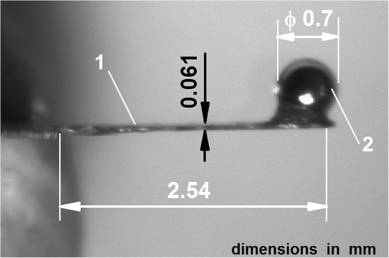
The cantilever used in our measurement. 1 cantilever beam (length 2.54 mm, width 0.41 mm, thickness 0.061 mm), 2 tip of the cantilever (a steel ball of 0.7-mm diameter).
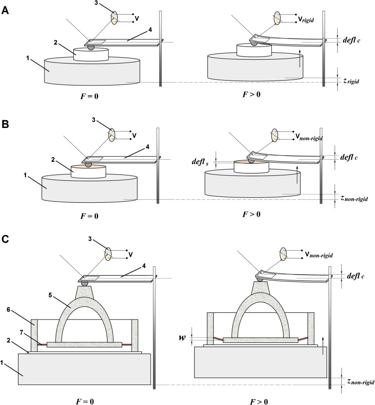
AFM-based nanomechanics measurements. F force acting between the sample and the tip, V voltage of the photodiode, defl
c deflection of the cantilever, defl
s deflection of the sample, w deflection of the AL of the stapes, z displacement of the piezoactuator. A Measurements on a rigid reference sample. The rigid surface acted as an infinitely stiff sample, i.e., a sample that cannot deform and only the cantilever bends. The resulting cantilever deflection is the same as the piezoactuator displacement (defl
c = z
rigid). 1 piezoactuator, 2 sample, 3 photodiode, 4 cantilever. B Measurements on a non-rigid sample. For the non-rigid samples, the measured deflection (defl
c) of the cantilever is not the same as the piezoactuator displacement (z
non-rigid), but defl
c = z
non ‐ rigid − defl
s. 1 piezoactuator, 2 sample, 3 photodiode, 4 cantilever. C Measurements on the AL sample. 1 piezoactuator, 2 glass cover slip, 3 photodiode, 4 cantilever, 5 stapes, 6 oval window bone, 7 annular ligament of the stapes.

The AL plate. The AL plate is a circular plate of diameter 2a with a central hole of diameter 2b. The AL plate is composed of n elastic fiber plates separated by amorphous substance. On the outer periphery, the AL plate is simply supported. The AL plate is subjected to a uniformly distributed load F/2πb (in N/m) around the edge of the central hole. 1 central hole (where the SF is placed), 2 annular ligament plate, 3 oval window bone, 4 single elastic fiber plate, 5 amorphous substance.
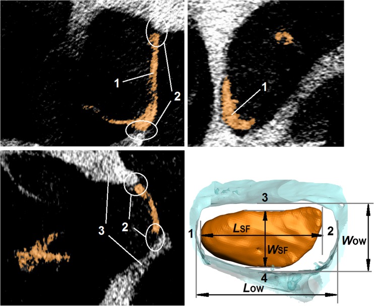
Morphometric measurements of the stapes footplate (SF) and the oval window (OW) based on micro-CT imaging with the use of the Measure Tool in ScanIP software (Simpleware Ltd, UK). 1 stapes footplate (SF), 2 annular ligament (AL), 3 oval window (OW) bone. L
OW length of the OW, W
OW width of the OW, L
SF length of the SF, W
SF width of the SF (dimensions are listed in Table 1).
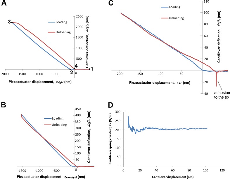
A Calibration curves (the calibration of the deflection sensor) recorded on the rigid reference sample (silicon wafer). 1 start point, 2 contact point, 3 maximum load, 4 out of contact. B Force-distance curves recorded on the reference sample (calibration structure 12Z00010, Nanoidea Ltd., Piaseczno nearby Warsaw, Poland, http://www.nanoidea.pl ). C Measurement curves recorded on the AL sample. D Real spring constant (k
c) of the self-made cantilever determined based on the calibration curves. The cantilever beam (length 2.54 mm, width 0.41 mm) etched out of the 60-μm beryllium copper plate (Alloy Brush 190 CuBe2, Lamineries Matthey SA, La Neuveville, Switzerland).

The force-deflection (F-w) curves for the two AL specimens. F force acting between the sample and the cantilever, w the AL deflection (where w = z
AL − defl
c according to Eq. 7 and Figure 5C). Colored lines—the curves for single measurements, black lines—the approximated curves.

The AL elastic modulus (E) calculated for various values of the AL thickness (h from 0.2 to 0.3 mm). The calculations based on Eq. 12. For Specimen 1 and Specimen 2, the following values were adopted: a
1 = 1.09 mm, b
1 = 0.99 mm, α
1 = 115.8 N/m and a
2 = 1.03 mm, b
2 = 0.94 mm, α
1 = 124.6 N/m, respectively. On the graph, the E values for the average h
1 = 0.24 mm and h
2 = 0.22 mm are shown.
References
-
- Asai M, Huber A, Goode R. Analysis of the best site on the stapes footplate for ossicular chain reconstruction. Acta Otolaryngol (Stockh) 1999;119(5):356–361. - PubMed
MeSH terms
LinkOut - more resources
Full Text Sources
Other Literature Sources
Miscellaneous
