. 2015 Jun 23;112(25):7639-44.
doi: 10.1073/pnas.1502939112. Epub 2015 Jun 8.

Selective buckling via states of self-stress in topological metamaterials

Affiliations

Selective buckling via states of self-stress in topological metamaterials

Jayson Paulose et al. Proc Natl Acad Sci U S A. .

Abstract

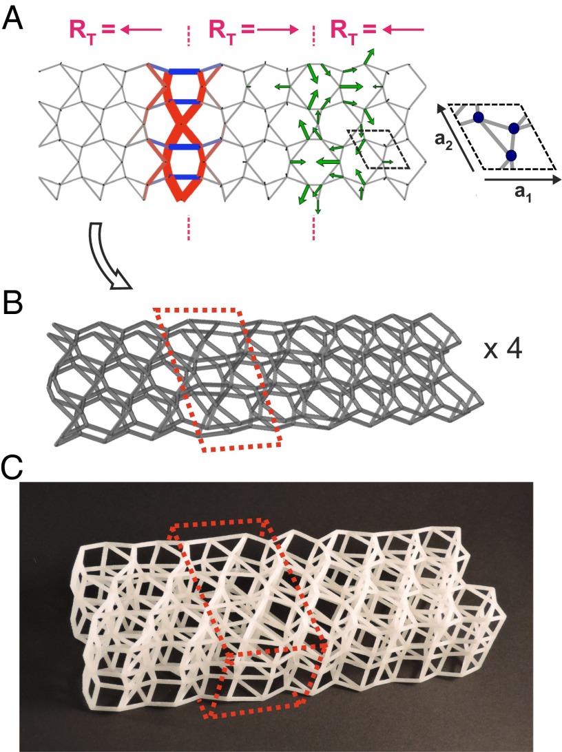
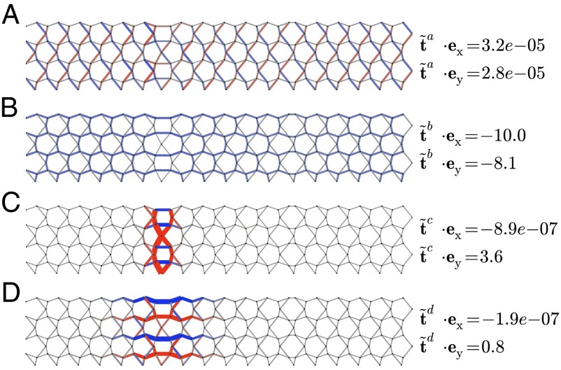
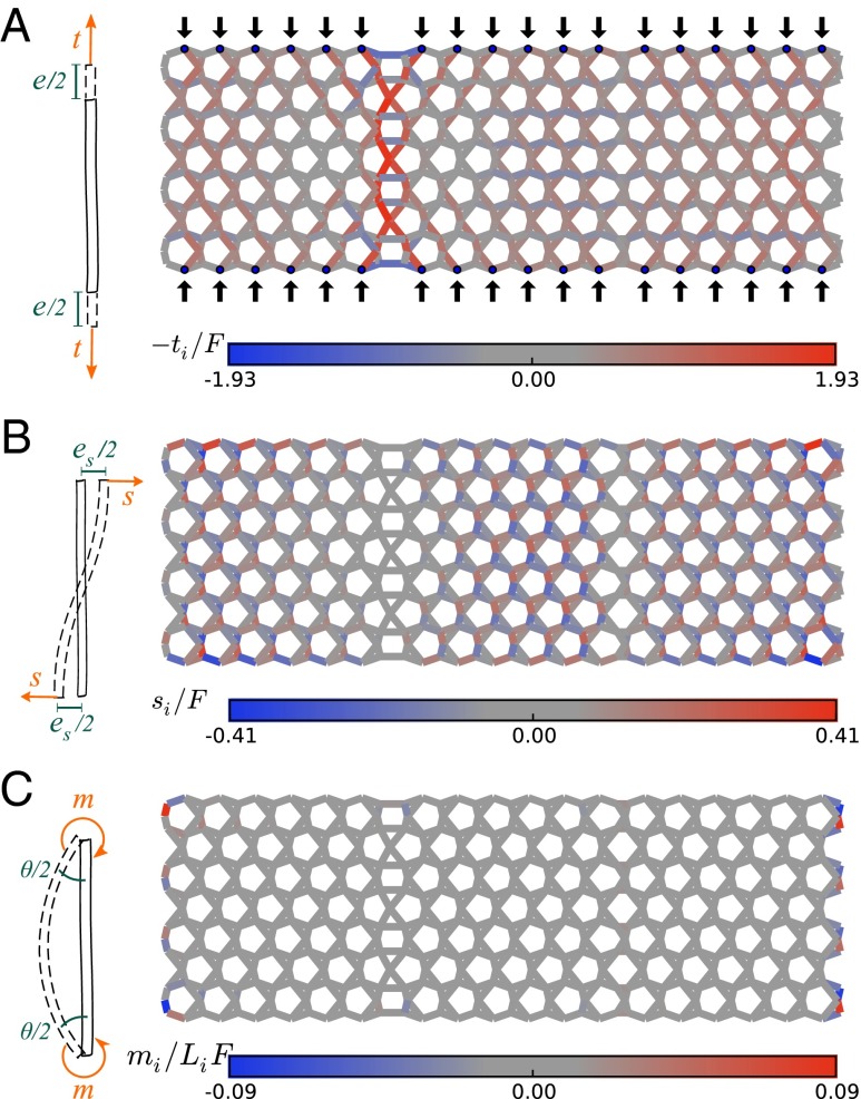
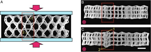
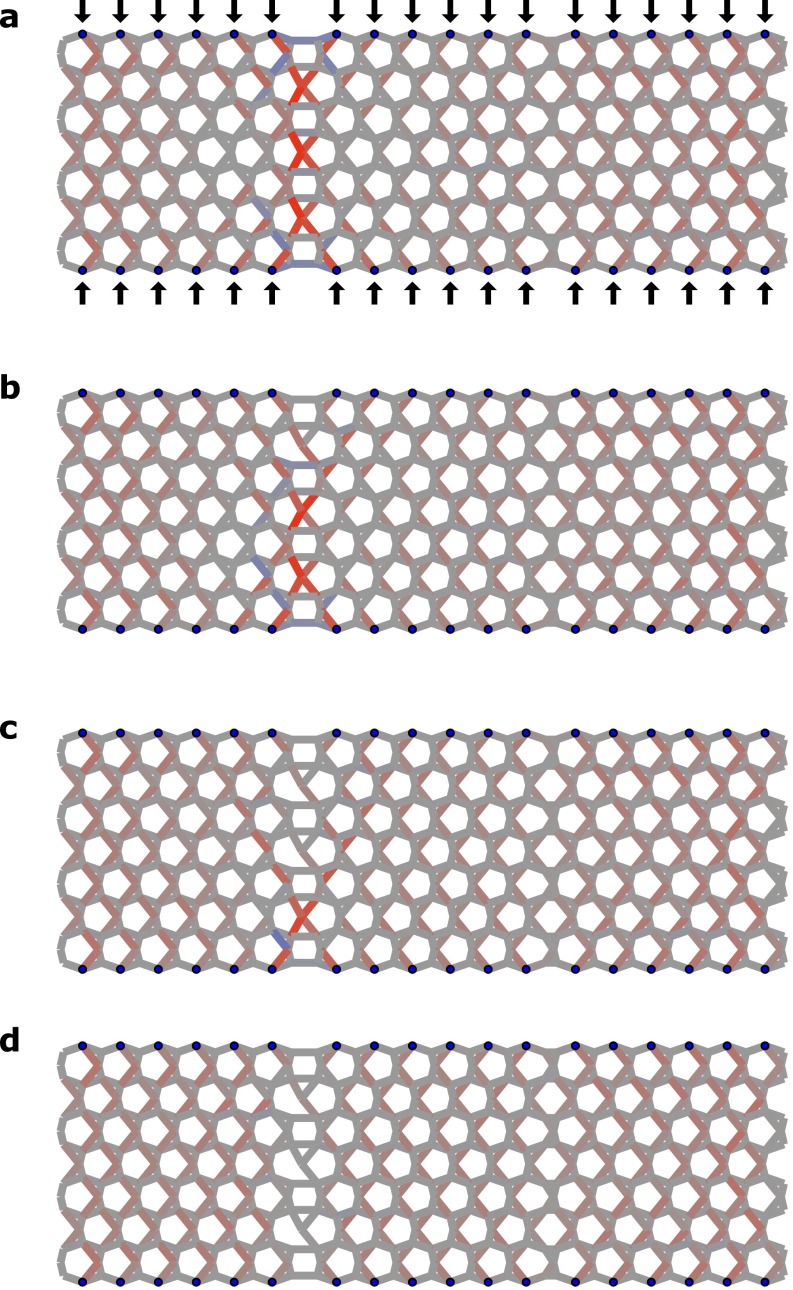
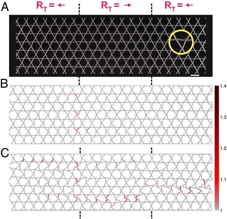
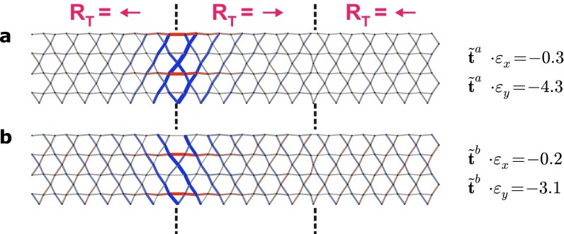
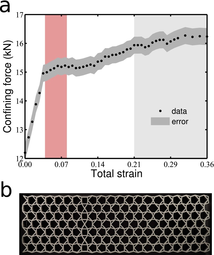
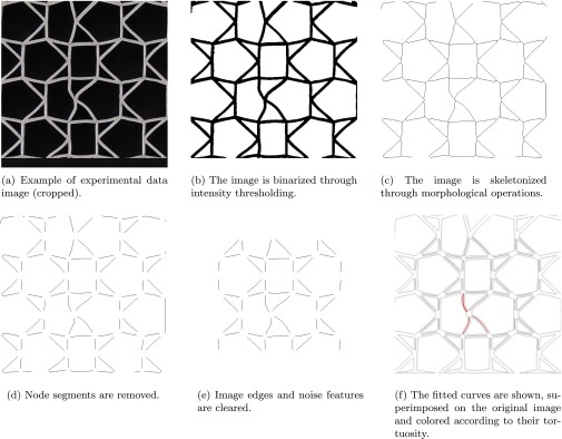
States of self-stress--tensions and compressions of structural elements that result in zero net forces--play an important role in determining the load-bearing ability of structures ranging from bridges to metamaterials with tunable mechanical properties. We exploit a class of recently introduced states of self-stress analogous to topological quantum states to sculpt localized buckling regions in the interior of periodic cellular metamaterials. Although the topological states of self-stress arise in the linear response of an idealized mechanical frame of harmonic springs connected by freely hinged joints, they leave a distinct signature in the nonlinear buckling behavior of a cellular material built out of elastic beams with rigid joints. The salient feature of these localized buckling regions is that they are indistinguishable from their surroundings as far as material parameters or connectivity of their constituent elements are concerned. Furthermore, they are robust against a wide range of structural perturbations. We demonstrate the effectiveness of this topological design through analytical and numerical calculations as well as buckling experiments performed on two- and three-dimensional metamaterials built out of stacked kagome lattices.

Keywords: isostatic lattices; topological mechanics; topological modes; tunable failure.


Conflict of interest statement

The authors declare no conflict of interest.

Figures

Fig. 1.
Fig. 1.
Topological buckling zone in a cellular metamaterial. (A) Isostatic frame containing two domain walls that separate regions built out of opposite orientations of the same repeating unit (boxed; the zoom shows the three unique hinges in the unit cell as disks). This unit cell carries a polarization RT=a1 (solid arrow), and the periodic frame displays topological edge modes (14). The left domain wall harbors topological states of self-stress, one of which is visualized by thickened beams identifying equilibrium-maintaining tensions (red) and compressions (blue) with magnitudes proportional to the thickness. The right domain wall harbors zero modes, one of which is visualized by green arrows showing relative displacements that do not stretch or compress the beams. Modes were calculated using periodic boundary conditions. (B) A 3D cellular metamaterial is obtained by stacking four copies of the beam geometry in A, and connecting equivalent points with vertical beams to obtain a structure with each interior point connecting six beams. The beams are rigidly connected to each other at the nodes and have a finite thickness. Points are perturbed by random amounts in the transverse direction and a small offset is applied to each layer to break up straight lines of beams. A 3D-printed realization of the design made of flexible plastic (Materials and Methods) is shown in C. The sample has a unit cell size of 25 mm and beams with circular cross-section of 2 mm diameter. The stacking creates a pile-up of states of self-stress in a quasi-2D region, highlighted by dotted lines.
Fig. 2.
Fig. 2.
Extended and localized states of self-stress of the frame. (AD) States of self-stress in the infinite periodic frame obtained by tiling the design of Fig. 1A in both directions. The states A and B are largely uniform over the structure, whereas C and D are localized to the left domain wall. The overlaps of each state of self-stress with the affine strains ex and ey (main text) are also shown. Only states of self-stress with significant overlaps are shown; all other states of self-stress in the structure have t˜qe{x,y}<105.
Fig. 3.
Fig. 3.
Stretching, shear, and bending contributions to the linear in-plane response of the cellular metamaterial. Response of a planar cellular structure, related to the lattice in Fig. 2 but with free edges, subject to a vertical compressive force F (solid arrows) at each point highlighted along the top and bottom edges. The structure is modeled as a network of flexible beams connected by rigid joints at the nodes, and with each beam providing torsional stiffness in addition to axial stiffness. The beams are colored according to (A) axial compression; (B) shear load; and (C) bending moment.
Fig. 4.
Fig. 4.
Buckling in the 3D topological cellular metamaterial. (A) Top view of the 3D sample (constructed as outlined in Fig. 1) showing the compression applied by confining the sample between transparent plates in contact with the front and back surfaces. The buckling zone is highlighted in red as in Fig. 1. Two vertical columns within this zone are labeled in yellow. Magenta arrows show the compression direction. (B and C) View along the compression axis at compressions of 0 and 20%, respectively. The beams in the region with states of self-stress have buckled in the vertical direction, whereas other beams have largely deformed within their stacking planes. (Scale bar, 25 mm.)
Fig. S1.
Fig. S1.
Sequential removal of beams to recreate the effect of buckling in the linear response. (A) Axial compression of the cellular material shown in Fig. 3A under identical loading, but with beams colored by the propensity for buckling, tiLi2/F. The beam with the highest value of this quantity will be the first to buckle as the force F on the boundary points is ramped up. (B–D) Result of sequentially removing the beam with the highest propensity for buckling and recalculating the compressions in the remaining beams under the same axial loading.
Fig. 5.
Fig. 5.
Buckling is robust under polarization-preserving changes of the unit cell. (A) A 2D foam cellular prototype, whose unit cell maintains the topological polarization RT even though its distortion away from the regular kagome lattice is small (a zoom of the constituent triangles is shown within the yellow circle). The domain wall geometry is identical to that of the 3D sample, with the left domain wall localizing states of self-stress. (Scale bar, 2 cm.) (B) Response of the structure under a vertical compression of 4% with free left and right edges. The beams are colored by the tortuosity, the ratio of the initial length of the beam to the end-to-end distance of the deformed segment (color bar). (C) Response of the structure under 7% compression, with beams colored by tortuosity using the same color scale as in B.
Fig. S2.
Fig. S2.
Localized states of self-stress for frame corresponding to design of Fig. 5A. The numerically obtained states of self-stress for a frame with the same domain wall geometry as in Fig. 2, but with the unit cell parameterized by (x1,x2,x3)=(0.025,0.025,0.025) which has a smaller distortion away from the regular kagome lattice and is used in Fig. 5A. The left domain wall still has a net outflux of the topological polarization and localizes states of self-stress, which have a significant overlap with the affine bond extensions ex and ey associated with uniform strains along x and y, respectively. Two independent states of self-stress exist with a significant overlap, shown in A and B.
Fig. S3.
Fig. S3.
Measurement of the total confining force as a function of imposed strain for a 2D cellular prototype sample (Fig. 5). (A) The measured data (black circles) and an estimate of the measurement error (dark gray contour) are shown. The red region indicates the strain regime in which the beams within the topologically rigid domain wall buckle. In the light gray region, the sample response is dominated by out-of-plane buckling of the entire sample rather than by in-plane deformations of the cellular structure. The error was estimated at 0.2 kN based on uncertainties in the compression and force due to the rudimentary measurement apparatus; (B) the 2D cellular prototype for which the load-compression curve was measured. Its unit cell in the outer region is parameterized by (x1,x2,x3)=(0.085,0.085,0.085).
Fig. S4.
Fig. S4.
Demonstration of steps in the image analysis process.

References

    1. Lakes R. Foam structures with a negative Poisson’s ratio. Science. 1987;235(4792):1038–1040. - PubMed
    1. Kadic M, Buckmann T, Stenger N, Thiel M, Wegener M. On the practicability of pentamode mechanical metamaterials. Appl Phys Lett. 2012;100:191901.
    1. Shim J, et al. Harnessing instabilities for design of soft reconfigurable auxetic/chiral materials. Soft Matter. 2013;9:8198–8202.
    1. Babaee S, et al. 2013. 3D soft metamaterials with negative Poisson’s ratio. Adv Mater 25(36):5044–5049.
    1. Shan S, et al. Harnessing multiple folding mechanisms in soft periodic structures for tunable control of elastic waves. Adv Funct Mater. 2014;24(31):4935–4942.

Publication types