

Plasmonic silver quantum dots coupled with hierarchical TiO2 nanotube arrays photoelectrodes for efficient visible-light photoelectrocatalytic hydrogen evolution
- PMID: 26067850
- PMCID: PMC4464392
- DOI: 10.1038/srep10461
Plasmonic silver quantum dots coupled with hierarchical TiO2 nanotube arrays photoelectrodes for efficient visible-light photoelectrocatalytic hydrogen evolution
Abstract
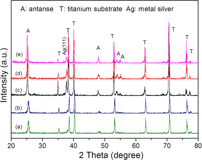
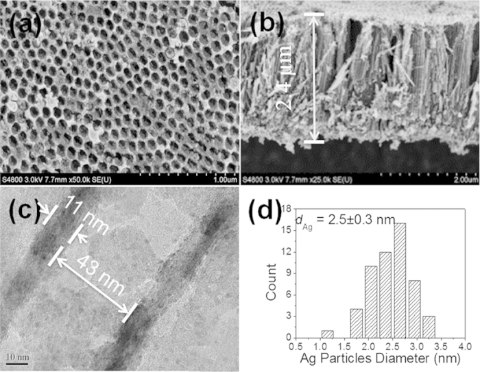
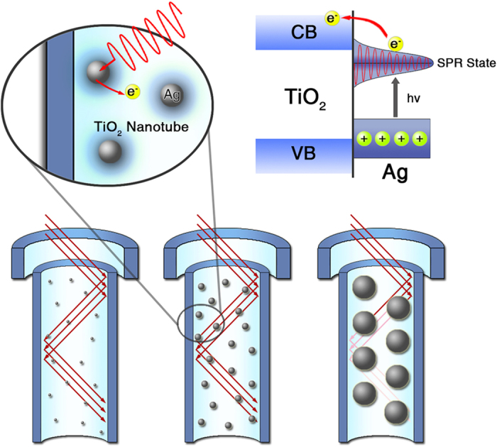
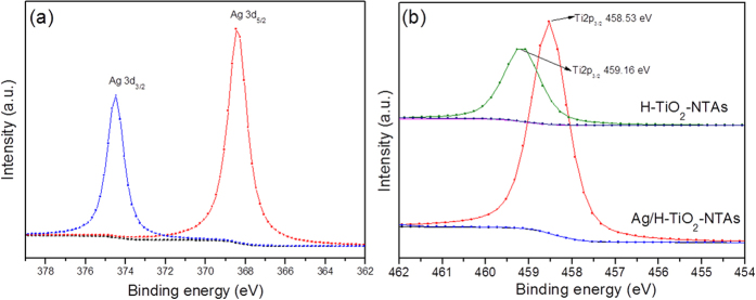
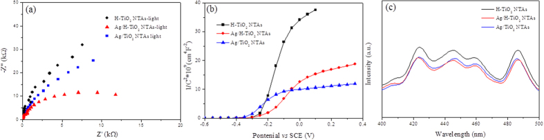
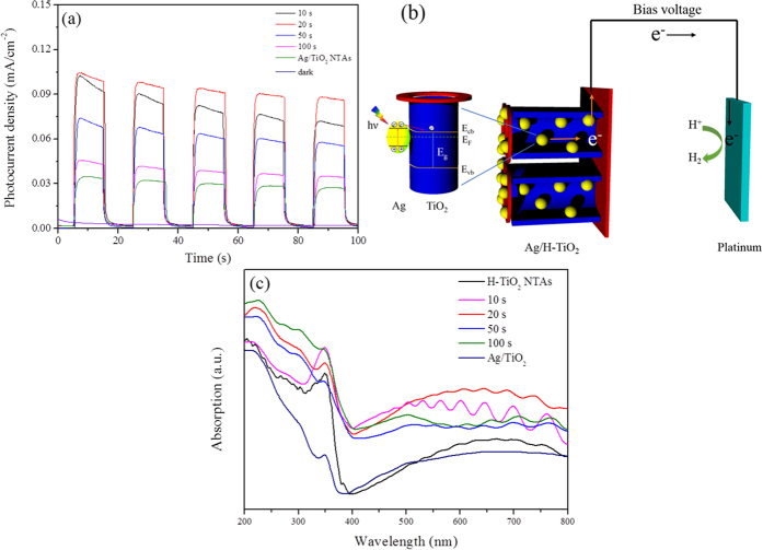
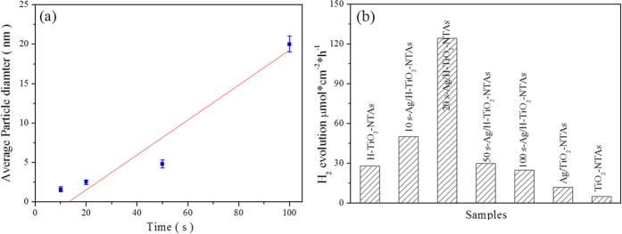
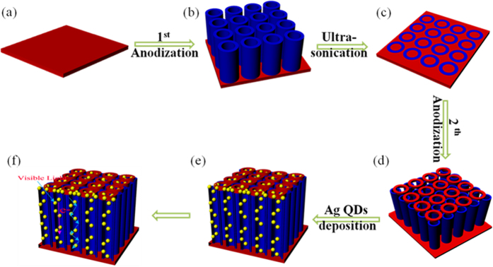
A plasmonic Ag/TiO2 photocatalytic composite was designed by selecting Ag quantum dots (Ag QDs) to act as a surface plasmon resonance (SPR) photosensitizer for driving the visible-light driven photoelectrocatalytic hydrogen evolution. Vertically oriented hierarchical TiO2 nanotube arrays (H-TiO2-NTAs) with macroporous structure were prepared through a two-step method based on electrochemical anodization. Subsequently, Ag QDs, with tunable size (1.3-21.0 nm), could be uniformly deposited on the H-TiO2 NTAs by current pulsing approach. The unique structure of the as-obtained photoelectrodes greatly improved the photoelectric conversion efficiency. The as-obtained Ag/H-TiO2-NTAs exhibited strong visible-light absorption capability, high photocurrent density, and enhanced photoelectrocatalytic (PEC) activity toward photoelectrocatalytic hydrogen evolution under visible-light irradiation (λ>420 nm). The enhancement in the photoelectric conversion efficiency and activity was ascribed to the synergistic effects of silver and the unique hierarchical structures of TiO2 nanotube arrays, strong SPR effect, and anti-shielding effect of ultrafine Ag QDs.
Figures
References
-
- Fujishima A. & Honda K. Electrochemical photolysis of water at a semiconductor electrode. Nature 238, 37–38 (1972). - PubMed
-
- El Ruby Mohamed A. & Rohani S. Modified TiO2 nanotube arrays (TNTAs): progressive strategies towards visible light responsive photoanode, a review. Energy Environ. Sci. 4, 1065–1086 (2011).
-
- Tahir A. A., Wijayantha K. G. U., Saremi-Yarahmadi S., Mazhar M. & McKee V. Nanostructured α-Fe2O3 thin films for photoelectrochemical hydrogen generation. Chem. Mater. 21, 3763–3772 (2009).
-
- Fu L., Yu H., Zhang C., Shao Z. & Yi B. Cobalt phosphate group modified hematite nanorod array as photoanode for efficient solar water splitting. Electrochem. Acta. 136, 363–369 (2014).
-
- Jang Y. H. et al. Correction to an unconventional route to high efficiency dye-sensitized solar cells via embedding graphitic thin films into TiO2 nanoparticle photoanode. Nano Lett. 12, 1742–1742 (2012). - PubMed
LinkOut - more resources
Full Text Sources
Other Literature Sources
