

The next evolution in radioguided surgery: breast cancer related sentinel node localization using a freehandSPECT-mobile gamma camera combination
- PMID: 26069857
- PMCID: PMC4446392
The next evolution in radioguided surgery: breast cancer related sentinel node localization using a freehandSPECT-mobile gamma camera combination
Abstract
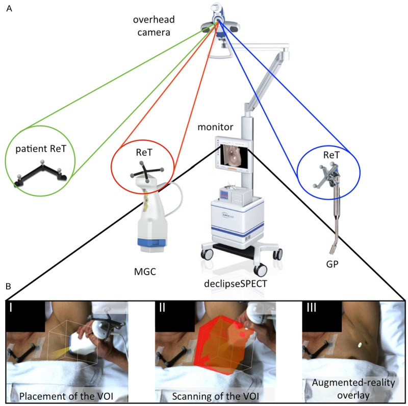
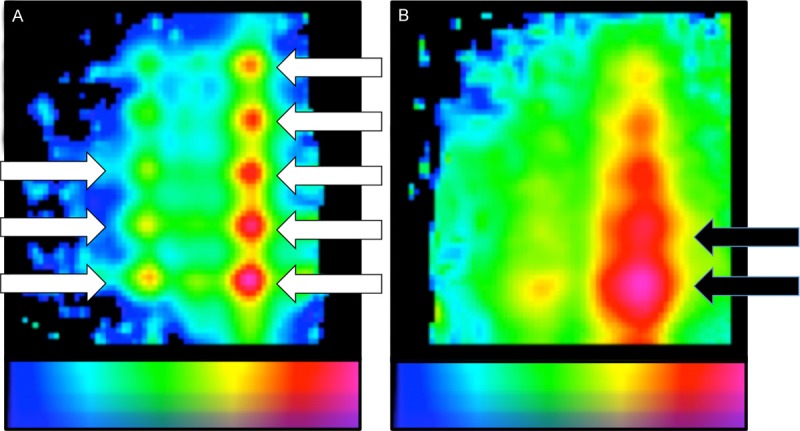
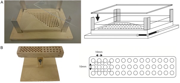
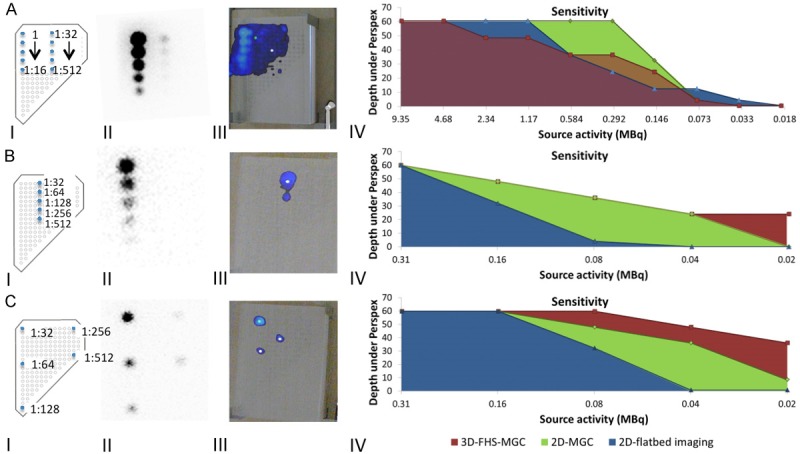
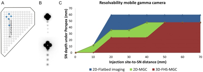
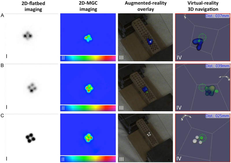
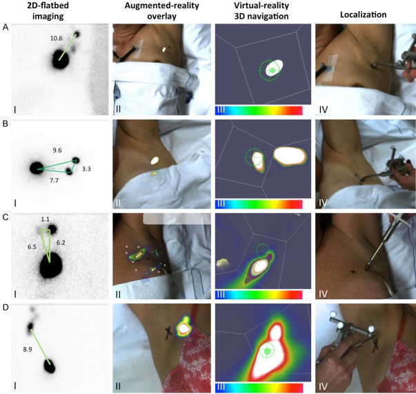
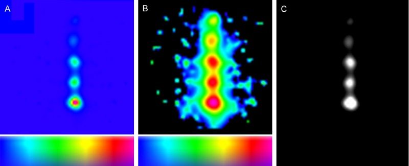
Accurate pre- and intraoperative identification of the sentinel node (SN) forms the basis of the SN biopsy procedure. Gamma tracing technologies such as a gamma probe (GP), a 2D mobile gamma camera (MGC) or 3D freehandSPECT (FHS) can be used to provide the surgeon with radioguidance to the SN(s). We reasoned that integrated use of these technologies results in the generation of a "hybrid" modality that combines the best that the individual radioguidance technologies have to offer. The sensitivity and resolvability of both 2D-MGC and 3D-FHS-MGC were studied in a phantom setup (at various source-detector depths and using varying injection site-to-SN distances), and in ten breast cancer patients scheduled for SN biopsy. Acquired 3D-FHS-MGC images were overlaid with the position of the phantom/patient. This augmented-reality overview image was then used for navigation to the hotspot/SN in virtual-reality using the GP. Obtained results were compared to conventional gamma camera lymphoscintigrams. Resolution of 3D-FHS-MGC allowed identification of the SNs at a minimum injection site (100 MBq)-to-node (1 MBq; 1%) distance of 20 mm, up to a source-detector depth of 36 mm in 2D-MGC and up to 24 mm in 3D-FHS-MGC. A clinically relevant dose of approximately 1 MBq was clearly detectable up to a depth of 60 mm in 2D-MGC and 48 mm in 3D-FHS-MGC. In all ten patients at least one SN was visualized on the lymphoscintigrams with a total of 12 SNs visualized. 3D-FHS-MGC identified 11 of 12 SNs and allowed navigation to all these visualized SNs; in one patient with two axillary SNs located closely to each other (11 mm), 3D-FHS-MGC was not able to distinguish the two SNs. In conclusion, high sensitivity detection of SNs at an injection site-to-node distance of 20 mm-and-up was possible using 3D-FHS-MGC. In patients, 3D-FHS-MGC showed highly reproducible images as compared to the conventional lymphoscintigrams.
Keywords: Sentinel node; breast cancer; freehandSPECT; mobile gamma camera; navigation; nuclear medicine; radioguided surgery.
Figures
Similar articles
-
Introducing navigation during melanoma-related sentinel lymph node procedures in the head-and-neck region.EJNMMI Res. 2017 Aug 17;7(1):65. doi: 10.1186/s13550-017-0312-1. EJNMMI Res. 2017. PMID: 28819936 Free PMC article.
-
Hybrid Surgical Guidance: Does Hardware Integration of γ- and Fluorescence Imaging Modalities Make Sense?J Nucl Med. 2017 Apr;58(4):646-650. doi: 10.2967/jnumed.116.177154. Epub 2016 Sep 29. J Nucl Med. 2017. PMID: 27688478
-
Multimodal hybrid imaging agents for sentinel node mapping as a means to (re)connect nuclear medicine to advances made in robot-assisted surgery.Eur J Nucl Med Mol Imaging. 2016 Jul;43(7):1278-87. doi: 10.1007/s00259-015-3292-2. Epub 2016 Jan 15. Eur J Nucl Med Mol Imaging. 2016. PMID: 26768422 Free PMC article.
-
Contribution of SPECT/CT imaging to radioguided sentinel lymph node biopsy in breast cancer, melanoma, and other solid cancers: from "open and see" to "see and open".Q J Nucl Med Mol Imaging. 2014 Jun;58(2):127-39. Q J Nucl Med Mol Imaging. 2014. PMID: 24835289 Review.
-
3D scintigraphic imaging and navigation in radioguided surgery: freehand SPECT technology and its clinical applications.Expert Rev Med Devices. 2016;13(4):339-51. doi: 10.1586/17434440.2016.1154456. Epub 2016 Mar 2. Expert Rev Med Devices. 2016. PMID: 26878667 Review.
Cited by
-
Evaluation of camera-based freehand SPECT in preoperative sentinel lymph node mapping for melanoma patients.EJNMMI Res. 2020 Nov 11;10(1):139. doi: 10.1186/s13550-020-00729-8. EJNMMI Res. 2020. PMID: 33175204 Free PMC article.
-
First-in-human evaluation of a hybrid modality that allows combined radio- and (near-infrared) fluorescence tracing during surgery.Eur J Nucl Med Mol Imaging. 2015 Oct;42(11):1639-1647. doi: 10.1007/s00259-015-3109-3. Epub 2015 Jun 25. Eur J Nucl Med Mol Imaging. 2015. PMID: 26109329
-
A radio- and fluorescently labelled tracer for imaging and quantification of bacterial infection on orthopaedic prostheses : a proof of principle study.Bone Joint Res. 2023 Jan;12(1):72-79. doi: 10.1302/2046-3758.121.BJR-2022-0216.R1. Bone Joint Res. 2023. PMID: 36649933 Free PMC article.
-
Hybrid surgical guidance based on the integration of radionuclear and optical technologies.Br J Radiol. 2016 Jun;89(1062):20150797. doi: 10.1259/bjr.20150797. Epub 2016 Mar 4. Br J Radiol. 2016. PMID: 26943463 Free PMC article. Review.
-
Feasibility and Performance of Free-Hand Single-Photon Computed Tomography/Ultrasonography for Preoperative Parathyroid Adenoma Localization: A Pilot Study.Diagnostics (Basel). 2023 Jun 28;13(13):2200. doi: 10.3390/diagnostics13132200. Diagnostics (Basel). 2023. PMID: 37443593 Free PMC article.
References
-
- Nieweg OE, Tanis PJ, Kroon BB. The definition of a sentinel node. Ann Surg Oncol. 2001;8:538–541. - PubMed
-
- Morton DL, Wen DR, Wong JH, Economou JS, Cagle LA, Storm FK, Foshag LJ, Cochran AJ. Technical details of intraoperative lymphatic mapping for early stage melanoma. Arch Surg. 1992;127:392–399. - PubMed
-
- Kim T, Giuliano AE, Lyman GH. Lymphatic mapping and sentinel lymph node biopsy in early-stage breast carcinoma: a metaanalysis. Cancer. 2006;106:4–16. - PubMed
-
- Schirrmeister H, Kotzerke J, Vogl F, Buck A, Czech N, Koretz K, Helm G, Kreienberg R, Kuhn T. Prospective evaluation of factors influencing success rates of sentinel node biopsy in 814 breast cancer patients. Cancer Biother Radiopharm. 2004;19:784–790. - PubMed
-
- Warncke SH, Mattei A, Fuechsel FG, Z’Brun S, Krause T, Studer UE. Detection rate and operating time required for gamma probe-guided sentinel lymph node resection after injection of technetium-99m nanocolloid into the prostate with and without preoperative imaging. Eur Urol. 2007;52:126–132. - PubMed
LinkOut - more resources
Full Text Sources