. 2015 Jun 26:6:7533.
doi: 10.1038/ncomms8533.

Kinetics and fracture resistance of lithiated silicon nanostructure pairs controlled by their mechanical interaction

Affiliations

Kinetics and fracture resistance of lithiated silicon nanostructure pairs controlled by their mechanical interaction

Seok Woo Lee et al. Nat Commun. .

Abstract

Following an explosion of studies of silicon as a negative electrode for Li-ion batteries, the anomalous volumetric changes and fracture of lithiated single Si particles have attracted significant attention in various fields, including mechanics. However, in real batteries, lithiation occurs simultaneously in clusters of Si in a confined medium. Hence, understanding how the individual Si structures interact during lithiation in a closed space is necessary. Here, we demonstrate physical and mechanical interactions of swelling Si structures during lithiation using well-defined Si nanopillar pairs. Ex situ SEM and in situ TEM studies reveal that compressive stresses change the reaction kinetics so that preferential lithiation occurs at free surfaces when the pillars are mechanically clamped. Such mechanical interactions enhance the fracture resistance of lithiated Si by lessening the tensile stress concentrations in Si structures. This study will contribute to improved design of Si structures at the electrode level for high-performance Li-ion batteries.


Figures

Figure 1
Figure 1. SEM study of the lithiation of a clamped <110> Si nanopillar.
(a,b) SEM images of <110> Si nanopillar positioned between adjacent rigid walls before (a) and after (b) lithiation. The electrochemical lithiation of a single pillar was suppressed by compressive stresses between the two rigid walls, which were supposed to be preferably grown to <110> direction as displayed in a schematic diagram (a). (c) Column chart of dimension change of <110> Si nanopillar along <110> (blue) and <100> (green) direction after lithiation when the pillar is unclamped and clamped. Single <110> Si nanopillar standing alone has preferential lithiation along <110> directions of Si but the clamped Si nanopillar shows further expansion along <100> direction.
Figure 2
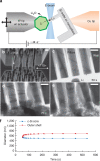
Figure 2. In situ TEM study of the lithiation of a clamped <110> Si nanopillar.
(a) A schematic image of the electrochemical cell configuration for in situ TEM observation. E-beam penetrates through <100> direction of Si nanopillar to observe a lateral <110> expansion during lithiation. (b) SEM image of pristine three pillars with adjacent rigid walls on both sides for in situ TEM observation. (ce) Time series of TEM images of the pillars during lithiation. All scale bars in SEM and TEM images are 500 nm. (f) The diameters of crystalline Si core and lithiated outer LixSi for the time line in the middle of lithiation. The lithiation cannot proceed further along <110> direction against the neighboring pillars due to the mechanical clamping.
Figure 3
Figure 3. Analytical model of the clamped Si pillar to predict the change of the driving force of the reaction.
(a) A schematic view of <110> crystalline Si with wall fixed at the end. The scheme represents morphological expansion and induced stresses during lithiation of <110> pillars and walls before the physical contact (‘Before contact', t2<g/2). (b) A schematic view of the one side of Si pillar contacted with the wall physically (‘After contact', t2≥g/2). The displacement of lithiated Si is confined as a half of the gap (g/2). (c) Normal (σn) and tangential (σt) stress at the interfaces in the crystalline Si and LixSi for the depth of lithiation (t1/t0) when g/t0 is 0.3. (d) Mean stress (σm) at the interfaces in the crystalline Si (solid) and LixSi (dotted) for the depth of lithiation (t1/t0) when g/t0 is 0.3. (e) Corresponding change of free energy due to mechanical stress (ΔGσ) for the depth of lithiation (t1/t0) when g/t0 is 0.3. Black dash line represents free energy of Li deposition versus free energy of lithiation of Si (formula image). Red vertical lines indicate the contact and reaction stoppage on lithiation of Si, respectively.
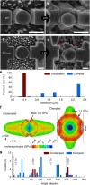
Figure 4
Figure 4. Improved fracture resistance of the clamped Si nanopillar on lithiation.
(a,b) SEM images of crystalline <110> Si pillar of 1-μm diameter and the walls with gap of 300 nm. The pillar is clamped by the walls and expanded along <100> direction upon lithiation. Significant crack is not found. (c,d) SEM images of crystalline <110> Si pillar of 2.2 μm diameter and the walls with gap of 300 nm. After lithiation, the cracks are found between <110> and <100> directions as indicated by red arrows. Scale bars, 1 μm. (e) Column chart of the fracture ratio of the clamped <110> Si pillars for various diameters. To compare the effect of mechanical clamping for the fracture resistance, the fracture ratio of unclamped <110> pillar is shown as red columns. (f) Finite element analysis of in-plane principal stress of unclamped (left) and clamped (right) <110> Si pillar after full lithiation. Initial diameter is 550 nm (dot circle) and lateral displacement of clamped pillar is confined to 160 nm (solid line). (g) Column chart of the population of the fracture location as an angle of the crack in the clamped <110> Si pillar upon lithiation (blue). The population of the fracture location of the unclamped <110> pillar (red) compares how mechanical clamping changes the fracture behaviour.

References

    1. Chan C. K. et al. High-performance lithium battery anodes using silicon nanowires. Nat. Nanotech. 3, 31–35 (2008). - PubMed
    1. Wu H. & Cui Y. Designing nanostructured Si anodes for high energy lithium ion batteries. Nano Today 7, 414–429 (2012).
    1. Whittingham M. S. Materials challenges facing electrical energy storage. MRS Bull. 33, 411–421 (2008).
    1. McDowell M. T., Lee S. W., Nix W. D. & Cui Y. Understanding the lithiation of silicon and other alloying anodes for lithium-ion batteries. Adv. Mater. 25, 4966–4985 (2013). - PubMed
    1. Kasavajjula U., Wang C. & Appleby a. J. Nano- and bulk-silicon-based insertion anodes for lithium-ion secondary cells. J. Power Sources 163, 1003–1039 (2007).

Publication types