. 2015 Jun 10:9:72.
doi: 10.3389/fncom.2015.00072. eCollection 2015.

A kinematic model for 3-D head-free gaze-shifts

Affiliations

A kinematic model for 3-D head-free gaze-shifts

Mehdi Daemi et al. Front Comput Neurosci. .

Abstract

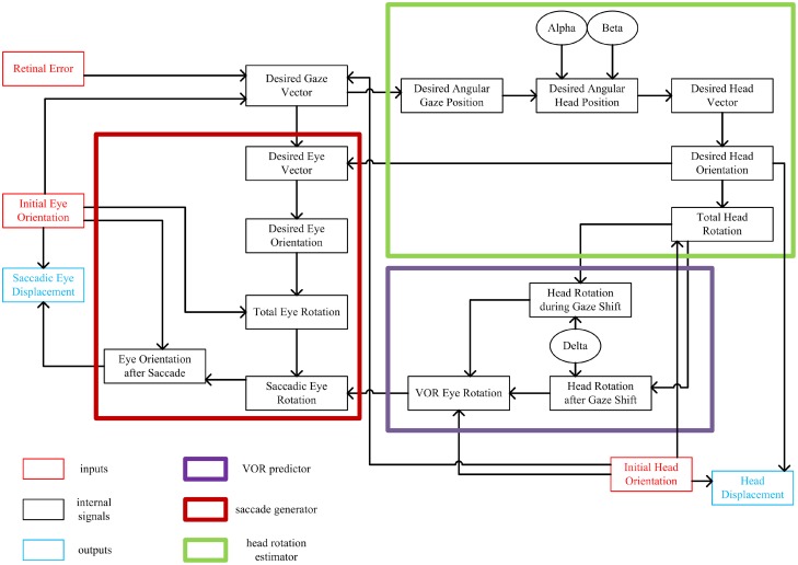
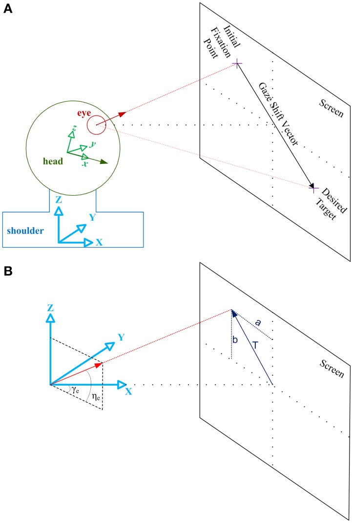
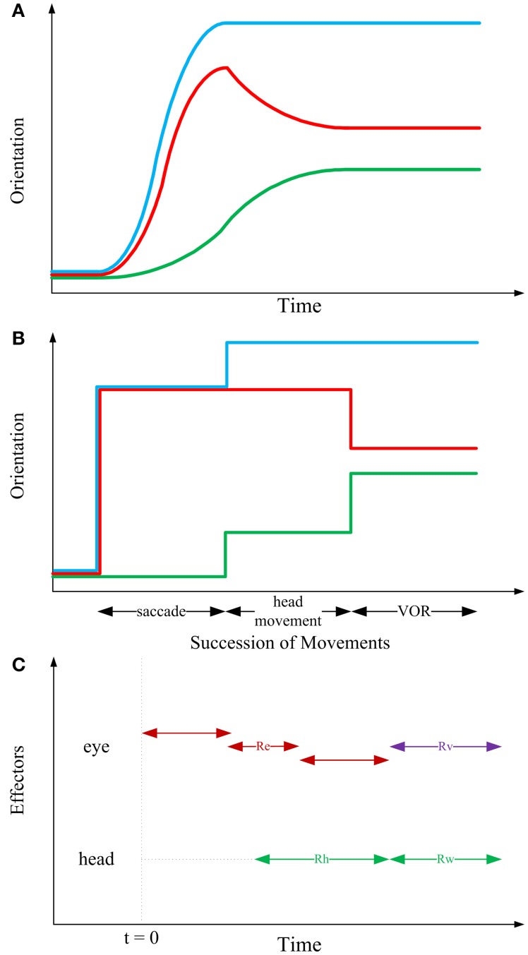
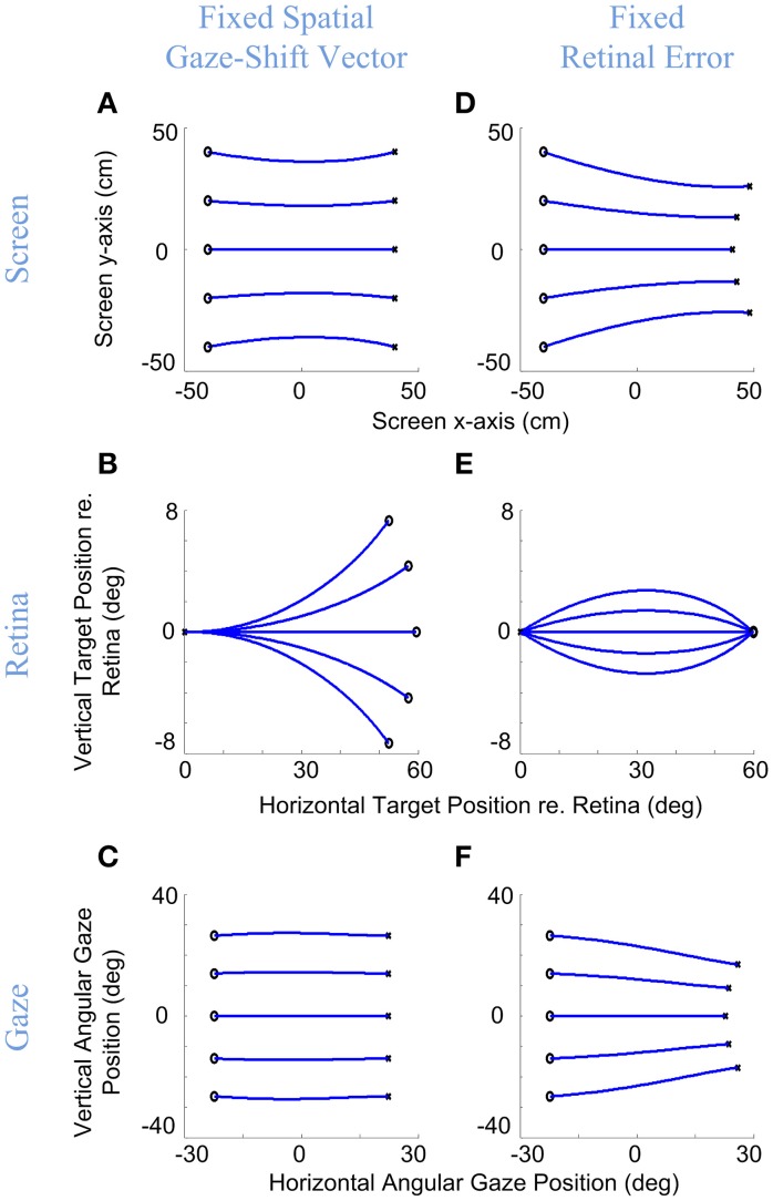
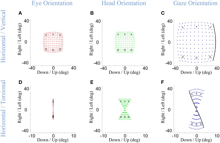
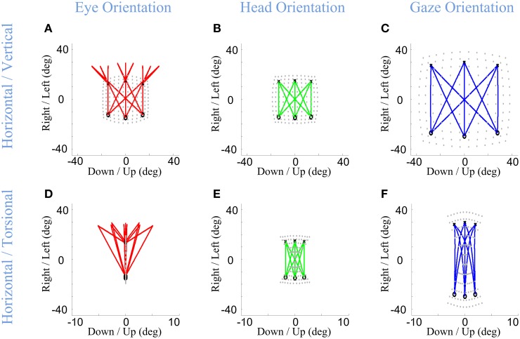
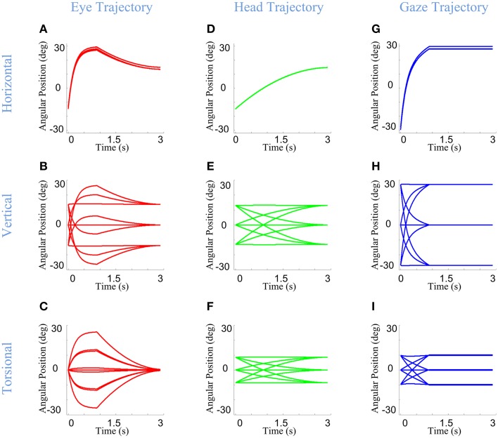
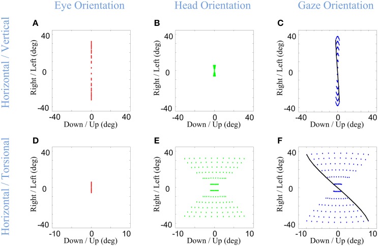
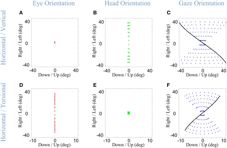
Rotations of the line of sight are mainly implemented by coordinated motion of the eyes and head. Here, we propose a model for the kinematics of three-dimensional (3-D) head-unrestrained gaze-shifts. The model was designed to account for major principles in the known behavior, such as gaze accuracy, spatiotemporal coordination of saccades with vestibulo-ocular reflex (VOR), relative eye and head contributions, the non-commutativity of rotations, and Listing's and Fick constraints for the eyes and head, respectively. The internal design of the model was inspired by known and hypothesized elements of gaze control physiology. Inputs included retinocentric location of the visual target and internal representations of initial 3-D eye and head orientation, whereas outputs were 3-D displacements of eye relative to the head and head relative to shoulder. Internal transformations decomposed the 2-D gaze command into 3-D eye and head commands with the use of three coordinated circuits: (1) a saccade generator, (2) a head rotation generator, (3) a VOR predictor. Simulations illustrate that the model can implement: (1) the correct 3-D reference frame transformations to generate accurate gaze shifts (despite variability in other parameters), (2) the experimentally verified constraints on static eye and head orientations during fixation, and (3) the experimentally observed 3-D trajectories of eye and head motion during gaze-shifts. We then use this model to simulate how 2-D eye-head coordination strategies interact with 3-D constraints to influence 3-D orientations of the eye-in-space, and the implications of this for spatial vision.

Keywords: Listing's law; gaze-shift; head movement; saccade; vestibulo-ocular reflex (VOR).


Figures

Figure 1
Figure 1
Flow of information in the static kinematic model. Red and blue rectangles show model inputs and outputs, respectively. Black ovals are the model parameters. Big thick red box shows the part of the model involved in computation of the saccadic eye movement. Big thick green box shows the part of the model which computes the head movement. Big thick violet box shows the VOR predictor. Each signal is computed from the signals that have inputs to it.
Figure 2
Figure 2
Illustration of the geometrical framework for studying head-free gaze-shift. (A) Head coordinate system, shown by the green axes fixed to the head, explains everything relative to the head. Shoulder or space coordinate system, shown by the blue axes fixed to the shoulder, explains everything relative to the space. Green vector is the head vector which is fixed to the head and moving with it. Red vector is the eye vector which connects center of the eye ball to the fovea. In the reference condition eye and head vectors are aligned in the same direction and intersect with the center of the screen. Eye vector defined in head coordinate system, e, is called eye-in-head vector and eye vector defined in space coordinate system, g, is called gaze vector. Head vector, h, is defined only relative to space. (B) Space coordinate system is drawn again to show how eye vector is characterized in space to represent the gaze vector. Gaze vector, or eye vector in space coordinates, is a unit vector which shows where the eye is fixating. Gaze vector can have a 2-D angular representation based on the angles [ηe, γe] it creates in spherical coordinates with the axes (the same applies to the head vector with angles [ηh, γh] not shown here). Gaze vector can be derived if we know where on the screen the subject is fixating, which is characterized by vector T.
Figure 3
Figure 3
Sequential structure of rotations in the kinematic model. In the first two panels, blue, red, and green curves, respectively depict gaze, eye-in-head and head trajectories. (A) Typical 1-D behavioral diagram from the experiments on natural head-unrestrained gaze-shift (Guitton et al., ; Freedman and Sparks, 1997). This observed pattern has inspired the sequence of events devised in the static kinematic model. (B) Succession of movements in the kinematic model. Head remains fixed while the eye is moving in the head. Then, head rotates, moving eye with itself such that eye-in-head position remains unchanged; this rotation foveates the target. Then, head rotates to its definite position, while eye rotates in head to compensate for head movement and keep the target foveated. (C) Having solved the equations of the model based on our physiologically inspired assumptions and constraints, we find that the saccadic eye movement has its independent axis and can be implemented in any duration of time which ends before onset of VOR (red double-headed arrows). Onset of head movement is arbitrary but its two parts are implemented continuously after each other (green double-headed arrows). Eye rotation during VOR is implemented right at the time when the second part of head movement is happening (violet double-headed arrow).
Figure 4
Figure 4
Gaze accuracy and the 3-D reference frame transformations for gaze-shifts. Rightward gaze-shifts are simulated from five different vertical altitudes with either a fixed symmetric horizontal gaze-shift, −40 cm left to 40 cm right, on a flat target screen (A–C), or from the same initial positions with a fixed retinal error of 60° right (D–F). First row shows the initial and desired target positions on the screen and the development of gaze direction on the screen during the gaze-shift. Second row shows the development of the target position in retinal coordinates during gaze-shift. Third row shows the development of the 2-D angular gaze position during gaze-shift. For both conditions, the model parameters are set to α = β = δ = 0.5. Circles show initial target locations while stars show the desired positions of target. Note that in (B) even though the targets are due right in spatial coordinates, they have variable vertical components in retinal coordinates, whereas conversely retinal errors in (E) start and end at the same positions, and correspond to different gaze trajectories.
Figure 5
Figure 5
Distributions of head, eye, and gaze orientations for equal contributions of eye and head rotations to horizontal and vertical directions. Model simulations producing gaze-shifts from the central fixation point (reference condition) to a uniform distribution of targets on the screen in range (−40, 40) degrees horizontal and (−40, 40) degrees vertical. The first (A,D), second (B,E), and third (C,F) columns, respectively, show eye-in-head (red), head-in-space (green), and eye-in-space orientations after the gaze-shift. First row illustrates the horizontal (right/left) against the vertical (up/down) components while the third row shows the horizontal (right-left) against the torsional (CW/CCW) components. The parameters of the model are set to α = β = δ = 0.5. The black curve shows gaze orientations for targets aligned horizontally on top of the screen.
Figure 6
Figure 6
Spatial path of the development of eye, head, and gaze orientations during gaze-shift. Three example gaze-shifts have been planned from three targets, vertically aligned at −40 cm on the screen, to another three targets, vertically aligned at 40 cm. The locations of eye, head, and gaze in initial condition are shown by circles while their locations in desired condition are shown by crosses. First (A–C) and second (D–F) rows show the temporal development of eye, head, and gaze in vertical-horizontal and torsional-horizontal planes, respectively.
Figure 7
Figure 7
Temporal pattern of development of eye, head, and gaze orientations during gaze-shift. For the same nine gaze-shifts, between two groups of vertically aligned targets, we have shown the development of the orientations. First (A–C), second (D–F), and third (G–I) columns show orientations of eye, head, and gaze, respectively. First, second, and third rows describe the development of horizontal, vertical, and torsional components of orientations, respectively.
Figure 8
Figure 8
Distributions of head, eye, and gaze orientations for two extreme cases of almost only eye contribution (head-fixed Saccade) and almost only head contribution. We have made the model to plan gaze-shifts from the central fixation point (reference condition) to a uniform distribution of targets on the screen in range (−40, 40) degrees horizontal and (−40, 40) degrees vertical. Eye-in-head (first column in red), head-in-space (second column in green), and eye-in-space (third column in blue) orientations are illustrated. Only the horizontal (right-left) against the torsional (CW/CCW) diagrams are included in this figure. The parameters of the model for the first row (A–C) is set to α = β = 0.15 and δ = 0.5 while for the second row (D–F) they are set to be α = β = 0.85 and δ = 0.5. The black curve shows gaze orientations for targets aligned horizontally on top of the screen.
Figure 9
Figure 9
Distributions of head, eye, and gaze orientations for two extreme cases of almost only head contribution to horizontal gaze-shift or almost only head contribution to vertical gaze-shift. We have made the model to plan gaze-shifts from the central fixation point (reference condition) to a uniform distribution of targets on the screen in range (−40, 40) degrees horizontal and (−40, 40) degrees vertical. Eye-in-head (first column in red), head-in-space (second column in green), and eye-in-space (third column in blue) orientations are illustrated. The horizontal (right-left) against the torsional (CW/CCW) diagrams are only included in this figure. The parameters of the model for the first row (A–C) is set to α = 0.05, β = 0.95, and δ = 0.5 while for the second row (D–F) they are set to be α = 0.95, β = 0.05, and δ = 0.5. The black curve shows gaze orientations for targets aligned horizontally on top of the screen.

Similar articles

Cited by

References

    1. Angelaki D. E., Dickman J. D. (2003). Premotor neurons encode torsional eye velocity during smooth-pursuit eye movements. J. Neurosci. 23, 2971–2979. - PMC - PubMed
    1. Bizzi E., Kalil R. E., Tagliasc V. (1971). Eye-head Coordination in monkeys - evidence for centrally patterned organization. Science 173, 452–454. 10.1126/science.173.3995.452 - DOI - PubMed
    1. Bizzi E., Kalil R. E., Morasso P. (1972). Two modes of active eye-head coordination in monkeys. Brain Res. 40, 45–48. 10.1016/0006-8993(72)90104-7 - DOI - PubMed
    1. Blohm G., Crawford J. D. (2007). Computations for geometrically accurate visually guided reaching in 3-D space. J. Vis. 7:4. 10.1167/7.5.4 - DOI - PubMed
    1. Blohm G., Khan A. Z., Ren L., Schreiber K. M., Crawford J. D. (2008). Depth estimation from retinal disparity requires eye and head orientation signals. J. Vis. 8, 3.1–23. 10.1167/8.16.3 - DOI - PubMed