Review
. 2015 Nov:49:1-16.
doi: 10.1016/j.preteyeres.2015.07.001. Epub 2015 Jul 2.

Corneal structure and transparency

Affiliations
Review

Corneal structure and transparency

Keith M Meek et al. Prog Retin Eye Res. 2015 Nov.

Abstract

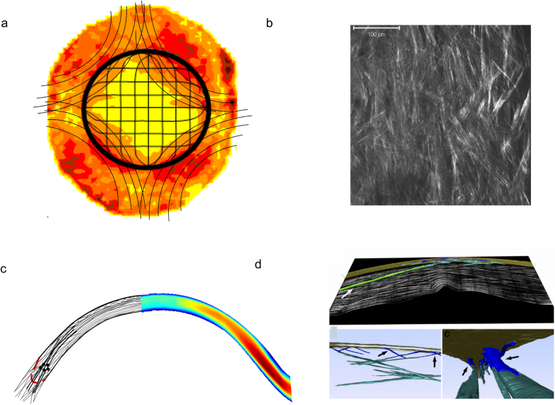
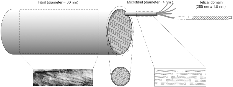
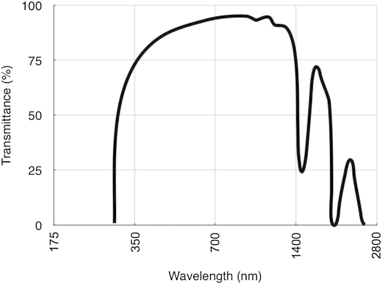
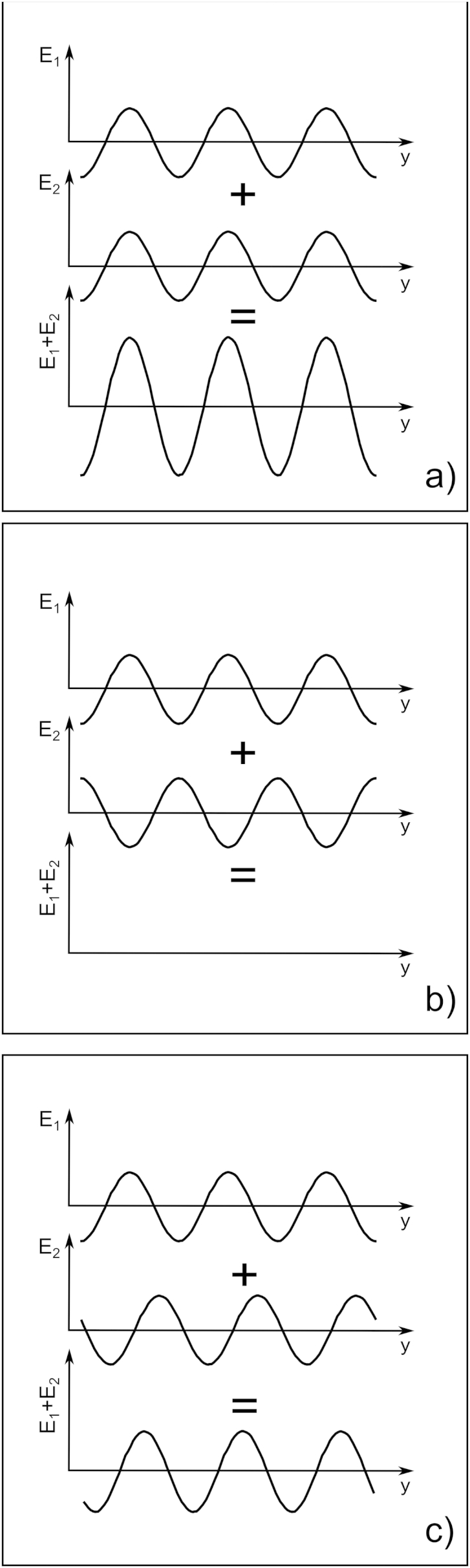
The corneal stroma plays several pivotal roles within the eye. Optically, it is the main refracting lens and thus has to combine almost perfect transmission of visible light with precise shape, in order to focus incoming light. Furthermore, mechanically it has to be extremely tough to protect the inner contents of the eye. These functions are governed by its structure at all hierarchical levels. The basic principles of corneal structure and transparency have been known for some time, but in recent years X-ray scattering and other methods have revealed that the details of this structure are far more complex than previously thought and that the intricacy of the arrangement of the collagenous lamellae provides the shape and the mechanical properties of the tissue. At the molecular level, modern technologies and theoretical modelling have started to explain exactly how the collagen fibrils are arranged within the stromal lamellae and how proteoglycans maintain this ultrastructure. In this review we describe the current state of knowledge about the three-dimensional stromal architecture at the microscopic level, and about the control mechanisms at the nanoscopic level that lead to optical transparency.

Keywords: Collagen; Cornea; Structure; Theoretical modelling; Three-dimensional electron microscopy; Transparency; X-ray.


Figures

Fig. 1
Fig. 1
Simplified model of the principal lamellar orientations in the human cornea. (a) and (c) are based on X-ray data; (b) and (d) are based on second harmonic generated (SHG) microscopy. (a) and (b) are en face views from the front of the cornea. The X-ray data (a) show the model (black lines) superimposed on the distribution of preferentially aligned collagen lamellae and indicates preferred lamellar orientations in the inferior-superior and nasal-temporal directions, predominantly in the posterior stroma. Many of these seem to become part of a circum-corneal annulus at the limbal region. In addition, anchoring lamellae with larger collagen fibrils are thought to enter the stroma in alignment with the extraocular musculature. The lines in the model show the predominant orientation of lamellae, not the actual course of individual lamellae. SHG microscopy from the posterior stroma (b) reveals an interwoven lattice of lamellae, such that adjacent lamellae are not orthogonal; thus no preferred orientation of collagen is obvious in the central cornea using this technique. (c) and (d) are views through the thickness of the stroma. In (c) the X-ray data are shown on the right. The corresponding model on the left suggests that lamellae are more interwoven anteriorly, particularly in the central 4 mm zone. Outside this zone, interweaving is more prominent in deeper stromal layers also. At the limbus (indicated by broken red line), the circumcorneal annulus appears in cross-section (represented by black circles) and anchoring lamellae appear to enter the stroma from the deeper layers and gradually move towards the surface. SHG microscopy (d) also demonstrates the highly interwoven anterior lamellae, which are often referred to as fibres using this imaging modality. A 3-D reconstruction shows bow spring fibres (blue), anchoring fibres inserting from the limbus (green), and the highly intertwined anterior fibre meshwork (teal) near Bowman's layer (gold). (d) is reproduced from Winkler et al. (2011) with permission of the copyright holder.
Fig. 2
Fig. 2
Structural hierarchy in corneal collagen (not to scale). Three helical alpha chains are supercoiled to produce the collagen triple helix molecule (top right). These molecules self-assemble in a staggered axial array (bottom right) to form microfibrils consisting of five molecules which in turn coil together to form the 30 nm diameter collagen fibrils seen in the electron microscope. The micrograph bottom left is reproduced from Ottani et al. (2002), with permission of the copyright holder, and shows the coiled microfibrils within the collagen fibril; the micrograph bottom middle is reproduced from Baldock et al. (2002), with permission of the copyright holder, and shows the microfibrils in cross-section within the collagen fibril.
Fig. 3
Fig. 3
Transmittance through the human cornea as a function of wavelength. Reproduced in part from Boettner and Wolter (1962) with permission of the copyright holder.
Fig. 4
Fig. 4
Wave interference of two one-dimensional sinusoidal waves. The two interfering waves are at the top of each panel and the resulting wave, which is a point by point sum of the interfering waves, at the bottom. In (a) the interfering waves are in phase. In (b) out of phase and in (c) they are shifted with respect to each other.
Fig. 5
Fig. 5
Secondary waves from a single (a) and pair (b) of collagen fibrils. The right hand side insets are a magnified view of the fibril arrangement contained in the rectangle in the main panels. The bar, 1 μm, is in common to (a) and (b).
Fig. 6
Fig. 6
Secondary waves from a collagen fibril distribution presenting short-range order. Primary incoming light is travelling from left to right (yellow arrow), with a wavelength of 500 nm. Collagen fibrils in transverse sections are represented by brown circles. All fibrils have the same diameter of about 31 nm, and no collagen fibrils can be closer than 62 nm. Only the intensity of the secondary radiation arising from the fibrils is shown in blue. No backwards secondary radiation can be seen in the figure. Bar 500 nm.
Fig. 7
Fig. 7
The effect of increased fibril diameters on light transmission. Secondary waves from the same collagen fibril distribution shown in Fig. 6. As before, primary incoming light is travelling from left to right (yellow arrow), with a wavelength of 500 nm. Collagen fibrils in transverse sections are represented by brown circles. 20% of the fibrils were selected at random and their diameter was doubled to 62 nm. The intensity of the secondary radiation arising from the fibrils is shown in blue. Backwards secondary radiation is evident in the figure (white arrows). Bar 500 nm.
Fig. 8
Fig. 8
The effect of fibril voids on light transmission. Secondary waves from the same collagen fibril distribution shown in Fig. 6. As before, primary incoming light is travelling from left to right (yellow arrow), with a wavelength of 500 nm. Collagen fibrils in transverse sections are represented by brown circles. Regions devoid of fibrils are now present (lakes). The intensity of the secondary radiation arising from the fibrils is shown in blue. Even in this case, backwards secondary radiation is evident in the figure (white arrow). Bar 500 nm.
Fig. 9
Fig. 9
Disordered Fibonacci quasi-crystal arrangement of fibrils. This type of quasi-crystal is deterministic over a long range. The radial distribution function (inset) plots the number of fibrils per unit area (normalized by dividing by the fibril number density in the image) separated by the distance shown on the horizontal axis. This is very similar to that seen from electron micrographs from the cornea (cf. Fig. 12b inset). Modified from Doutch (2009) with permission of the copyright holder.
Fig. 10
Fig. 10
Three-dimensional corneal stroma reconstruction.(a) Longitudinal section. (b) Transverse section. In both panels the collagen fibrils are depicted in orange and proteoglycans in yellow. Bars 100 nm. Modified from Lewis et al. (2010) with permission of the copyright holder.
Fig. 11
Fig. 11
The electrostatic restoring force mechanism which acts on fibrils to maintain the lattice organization. The mechanism is illustrated for the case where all fibrils in the lattice are held fixed in their lattice positions and a single fibril is displaced relative to its lattice position. (a) Shows a set of fibrils in a regular lattice arrangement with their associated GAG chains and a distribution of mobile ions. In this situation, which corresponds to normal physiological conditions, the osmotic pressure is essentially uniform. (b) Depicts the osmotic pressure in each subcell around the undisturbed fibril. The osmotic pressure in each subcell exerts a force on the fibril but because the osmotic pressure is uniform, all six forces balance and the net force is zero, as indicated by the red dot. (c) Shows a fibril displaced from its lattice position. The GAG chains attached to the fibril move with the fibril and the GAG fixed charge density and mobile ion concentration increase in advance of the fibril displacement and reduce behind it. (d) Indicates the resulting osmotic pressure in each of the subcells, which is higher where GAG fixed charge density has increased and lower where it has reduced. The forces exerted by each of the subcells now has changed magnitude with the result that a net force acts on the fibril with a direction oriented towards the original lattice position. This restoring force is shown as a red arrow. Figure and caption reproduced from Cheng and Pinsky (2013) with permission of the copyright holder.
Fig. 12
Fig. 12
Collagen fibril positions and corresponding radial distribution function (inset) from (a) a computer simulation and (b) a transmission electron micrograph of a rabbit cornea. The radial distribution function plots the number of fibrils per unit area (normalized by dividing by the fibril number density in the image) separated by the distance shown on the horizontal axis.
Fig. 13
Fig. 13
Calculated light transmission in the rabbit cornea as a function of wavelength for the collagen fibril distributions represented in Fig. 12a (grey curve) and Fig. 12b (black curve). Both curves were calculated using the direct summation of fields method (Freund et al., 1986), using other parameters taken from rabbit cornea (corneal thickness 360 microns, refractive index of collagen 1.355, refractive index of ground substance 1.420, collagen radius 19.4 nm, fibril density 220 fibrils per square micron).

References

    1. Abahussin M., Hayes S., Knox Cartwright N.E., Kamma Lorger C.S., Khan Y., Marshall J., Meek K.M. 3D collagen orientation study in human cornea using X-ray diffraction and femtosecond laser technology. Invest. Ophthalmol. Vis. Sci. 2009;50:5159–5164. - PubMed
    1. Abass A., Hayes S., White N., Sorensen T., Meek K.M. Transverse depth-dependent changes in corneal collagen lamellar orientation and distribution. J. R. Soc. Interface. 2015;12:20140717. - PMC - PubMed
    1. Aghamohammadzadeh H., Newton R.H., Meek K.M. X-ray scattering used to map the preferred collagen orientation in the human cornea and limbus. Structure. 2004;12:249–256. - PubMed
    1. Alexander R.A., Garner A. Elastic and precursor fibres in the normal human eye. Exp. Eye Res. 1983;36:305–315. - PubMed
    1. Alexander R.J., Silverman B., Henley W.L. Isolation and characterization of BCP-54, the major soluble protein of bovine cornea. Exp. Eye Res. 1981;32:205–216. - PubMed

Publication types