

Magnetic patterning: local manipulation of the intergranular exchange coupling via grain boundary engineering
- PMID: 26156786
- PMCID: PMC4496669
- DOI: 10.1038/srep11904
Magnetic patterning: local manipulation of the intergranular exchange coupling via grain boundary engineering
Abstract
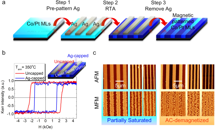
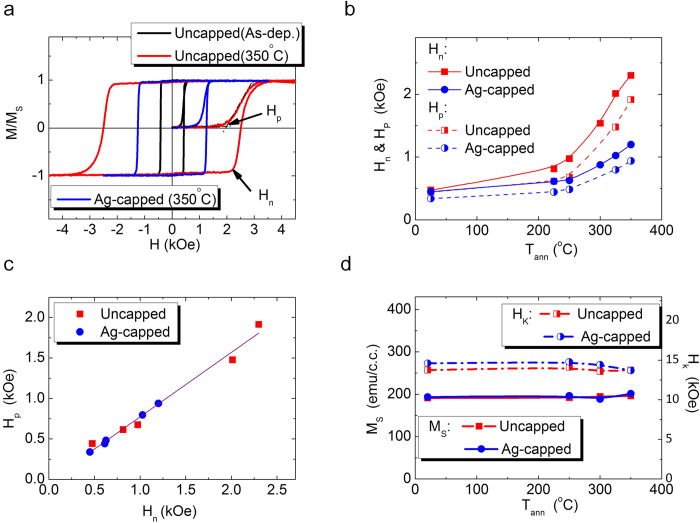
Magnetic patterning, with designed spatial profile of the desired magnetic properties, has been a rising challenge for developing magnetic devices at nanoscale. Most existing methods rely on locally modifying magnetic anisotropy energy or saturation magnetization, and thus post stringent constraints on the adaptability in diverse applications. We propose an alternative route for magnetic patterning: by manipulating the local intergranular exchange coupling to tune lateral magnetic properties. As demonstration, the grain boundary structure of Co/Pt multilayers is engineered by thermal treatment, where the stress state of the multilayers and thus the intergranular exchange coupling can be modified. With Ag passivation layers on top of the Co/Pt multilayers, we can hinder the stress relaxation and grain boundary modification. Combining the pre-patterned Ag passivation layer with thermal treatment, we can design spatial variations of the magnetic properties by tuning the intergranular exchange coupling, which diversifies the magnetic patterning process and extends its feasibility for varieties of new devices.
Figures


Similar articles
-
Domain size and structure in exchange coupled [Co/Pt]/NiO/[Co/Pt] multilayers.J Phys Condens Matter. 2011 Sep 21;23(37):376002. doi: 10.1088/0953-8984/23/37/376002. Epub 2011 Aug 31. J Phys Condens Matter. 2011. PMID: 21878718
-
Magnetic Anisotropies and Exchange Bias of Co/CoO Multilayers with Intermediate Ultrathin Pt Layers.Materials (Basel). 2023 Feb 7;16(4):1378. doi: 10.3390/ma16041378. Materials (Basel). 2023. PMID: 36837008 Free PMC article.
-
Patterning of magnetic thin films and multilayers using nanostructured tantalum gettering templates.ACS Appl Mater Interfaces. 2015 Mar 25;7(11):6014-8. doi: 10.1021/am5090463. Epub 2015 Mar 12. ACS Appl Mater Interfaces. 2015. PMID: 25761738
-
Topological defects and misfit strain in magnetic stripe domains of lateral multilayers with perpendicular magnetic anisotropy.Phys Rev Lett. 2012 Sep 14;109(11):117202. doi: 10.1103/PhysRevLett.109.117202. Epub 2012 Sep 11. Phys Rev Lett. 2012. PMID: 23005668
-
Manipulation of Superparamagnetic Beads on Patterned Exchange-Bias Layer Systems for Biosensing Applications.Sensors (Basel). 2015 Nov 13;15(11):28854-88. doi: 10.3390/s151128854. Sensors (Basel). 2015. PMID: 26580625 Free PMC article. Review.
Cited by
-
High thermal durability of Ru-based synthetic antiferromagnet by interfacial engineering with Re insertion.Sci Rep. 2021 Jul 26;11(1):15214. doi: 10.1038/s41598-021-94640-4. Sci Rep. 2021. PMID: 34312435 Free PMC article.
-
Spontaneous formation of spiral-like patterns with distinct periodic physical properties by confined electrodeposition of Co-In disks.Sci Rep. 2016 Jul 27;6:30398. doi: 10.1038/srep30398. Sci Rep. 2016. PMID: 27462025 Free PMC article.
-
Enhancement of infrared absorption through a patterned thin film of magnetic field and spin-coating directed self-assembly of gold nanoparticle stabilised ferrofluid emulsion.RSC Adv. 2023 Aug 10;13(34):23955-23966. doi: 10.1039/d3ra01369c. eCollection 2023 Aug 4. RSC Adv. 2023. PMID: 37577102 Free PMC article.
-
Direct Depth- and Lateral- Imaging of Nanoscale Magnets Generated by Ion Impact.Sci Rep. 2015 Nov 20;5:16786. doi: 10.1038/srep16786. Sci Rep. 2015. PMID: 26584789 Free PMC article.
References
-
- Chappert C. et al. Planar patterned magnetic media obtained by ion irradiation. Science 280, 1919–1922 (1998). - PubMed
-
- Ikeda S. et al. A perpendicular-anisotropy CoFeB-MgO magnetic tunnel junction. Nature materials 9, 721–724 (2010). - PubMed
-
- Allwood D. A. et al. Magnetic domain-wall logic. Science 309, 1688–1692 (2005). - PubMed
-
- Parkin S. S., Hayashi M. & Thomas L. Magnetic domain-wall racetrack memory. Science 320, 190–194 (2008). - PubMed
-
- Neusser S. & Grundler D. Magnonics: Spin Waves on the Nanoscale. Adv Mater 21, 2927–2932 (2009).
Publication types
LinkOut - more resources
Full Text Sources
Other Literature Sources
Molecular Biology Databases
Research Materials
