Review
. 2015 Jul;2(3):031205.
doi: 10.1117/1.NPh.2.3.031205. Epub 2015 Jul 2.

Optrodes for combined optogenetics and electrophysiology in live animals

Affiliations
Review

Optrodes for combined optogenetics and electrophysiology in live animals

Suzie Dufour et al. Neurophotonics. 2015 Jul.

Abstract

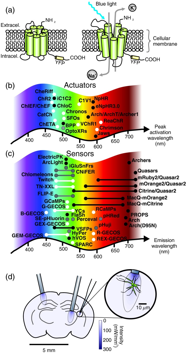
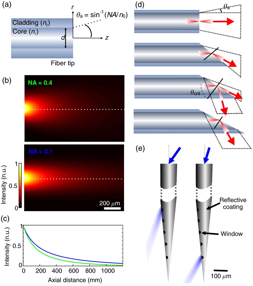
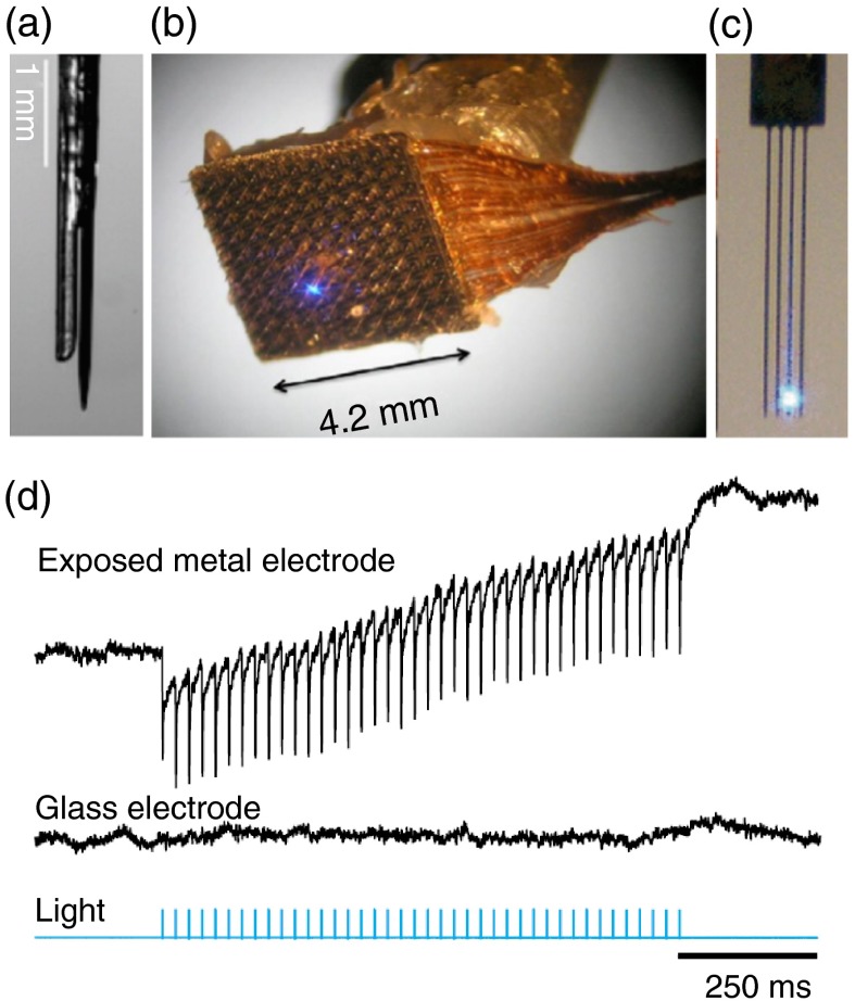
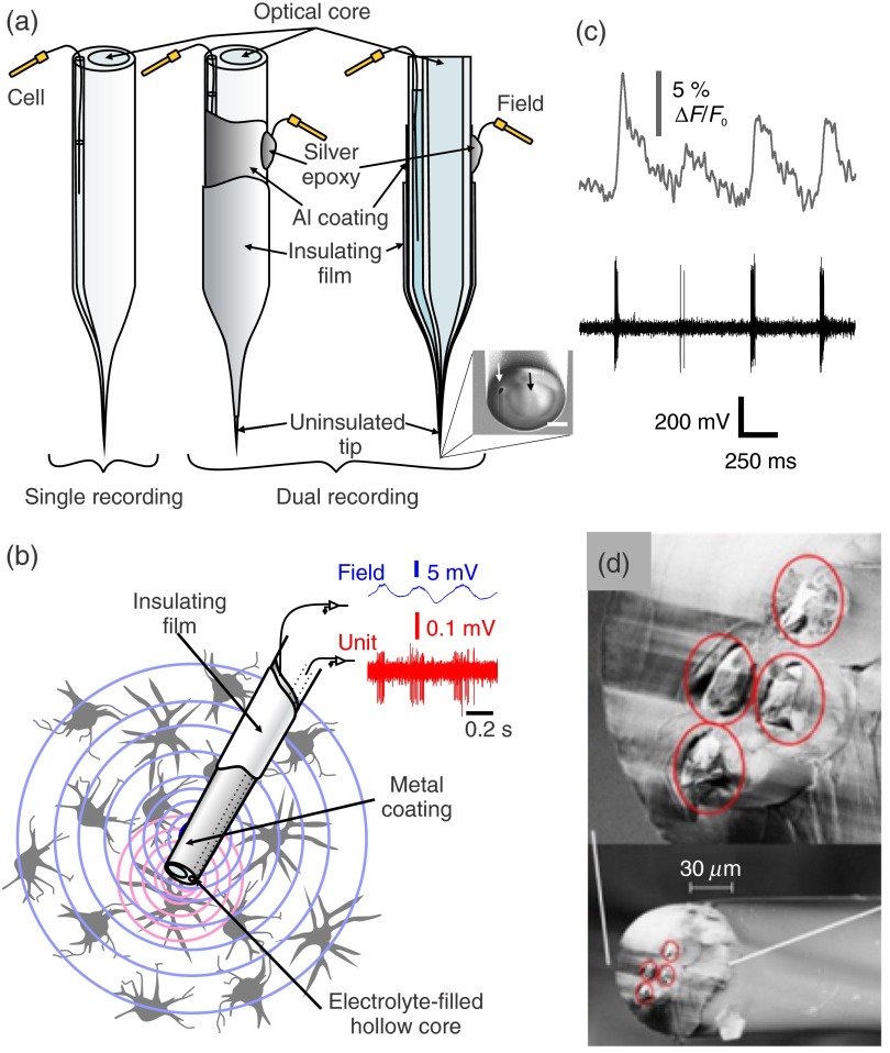
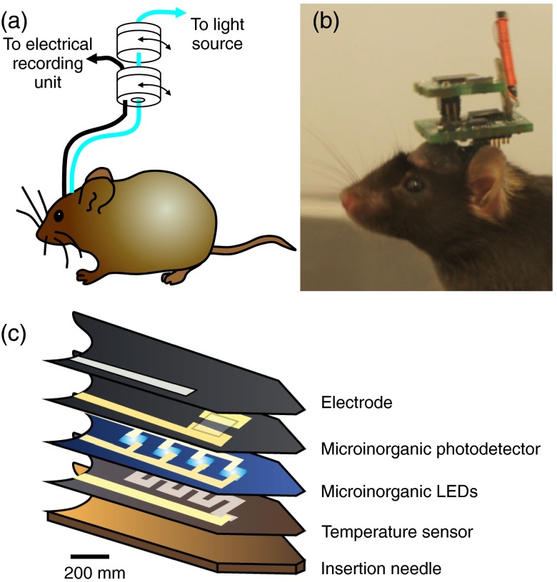
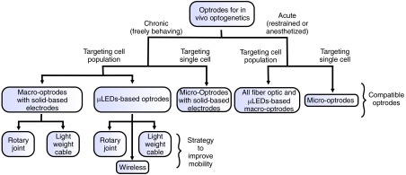
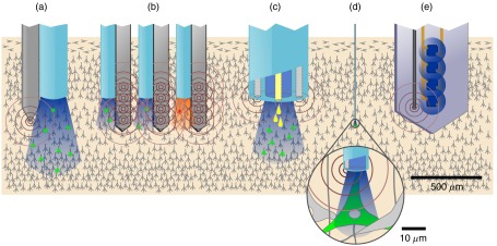
Optical tissue properties limit visible light depth penetration in tissue. Because of this, the recent development of optogenetic tools was quickly followed by the development of light delivery devices for in vivo optogenetics applications. We summarize the efforts made in the last decade to design neural probes that combine conventional electrophysiological recordings and optical channel(s) for optogenetic activation, often referred to as optodes or optrodes. Several aspects including challenges for light delivery in living brain tissue, the combination of light delivery with electrophysiological recordings, probe designs, multimodality, wireless implantable system, and practical considerations guiding the choice of configuration depending on the questions one seeks to address are presented.

Keywords: fiber optics; genetically-encoded sensors; light-tissue interactions; neuroscience; opsins.


Figures

Fig. 1
Fig. 1
Optogenetic tools and light tissue penetration: (a) schematic representation of a transmembrane channelrhodopsin protein in its closed (left) and opened (right) configurations following blue light illumination; (b) and (c) schematic representation of the peak activation wavelength of the actuator (white)/silencing (black) proteins listed in Table 1(b) and the fluorescent sensor proteins [voltage (black), calcium (white), and other sensors (gray)] listed in Table 2. Proteins for intracellular signaling control in panel b are represented in gray; (d) schematic representation of a coronal cross-section of a mouse brain illustrating the typical light penetrance achieved (distribution of irradiance, calculated using the equation in the Appendix) at 473 nm using a 200-μm diameter optical fiber (NA=0.2) and a micro-optrode.
Fig. 2
Fig. 2
Tissue irradiance profiles and strategies for controlled light delivery: (a) schematic representation of an optical fiber tip and the calculated irradiance profile (b) at its tip for NA=0.4 and NA=0.1; the diameter of the fiber core used in the calculation was 200μm and values of absorption and scattering were chosen for a wavelength of 473 nm; (c) axial normalized intensity profile at fiber center, corresponding to the dashed lines in (b); (d) different irradiance profile obtained from different tip geometries (adapted from Vo-Dinh70); (e) flexible illumination location from a coated tapered fiber (adapted from Ref. 71). Optical windows (5μm wide) were made along the tapered shaft. Using different light input angles, different zones are illuminated.
Fig. 3
Fig. 3
Optrode designs: (a) optrode design made from a 62.5μm core multimode fiber and a metal recording electrode; (b) integrated device that combines a multielectrode array and a fine illumination site; (c) multiarray silicon probes with integrated optical fibers for spatiotemporal brain control and recording; and (d) simultaneous local field potential recordings from mice tissue not expressing opsins with light-exposed metal (upper trace) and glass microelectrodes (middle trace). Light stimulation is represented in blue. Note the photo-electric artifacts in the upper trace (modified from Ref. 74).
Fig. 4
Fig. 4
Micro-optrodes made from customized optical fibers: (a) schematic representation of a tapered dual-core fiber (left). One core (optical-core) serves as an optical channel and the second, a hollow core, is filled with an electrolyte to serve as an extracellular single unit recording electrode. Metal coatings can be added further on the external wall of the fiber to provide additional extracellular local field potential recording capabilities. The middle panel shows a three-dimensional view of the coated probe and the right panel a transverse cut view. The inset is a scanning electron micrograph of the fiber tip (scale bas is 2μm). The white arrow points at the hollow core used for electrical recording and the black arrow points at the optical core. (b) Schematic representation of the electrophysiological signals recorded with the metal coated fiber (wide field potentials) versus the electrolyte-filled hollow core (single unit spikes) of the same fiber. (c) Example of simultaneous cellular level electrophysiological and calcium monitoring (adapted from Ref. 9). (d) Micrograph of a flexible optitrode made from polymer and embedded twisted-wire tetrode (modified from Ref. 105).
Fig. 5
Fig. 5
Multimodal optogenetics configurations for experiments in freely moving animals: (a) representation of a mouse implanted with a fiber optic cannula and a chronic electrophysiogical electrode and the rotary joints enabling free movements of the animal; (b) image of a mouse implanted with a wireless optogenetic system (Figure modified from Ref. 110); (c) schematics of the layer composition of multifunctional, implantable optoelectronic device incorporating various elements that can be used for wireless optogenetics and electrophysiology (adapted from Ref. 117).
Fig. 6
Fig. 6
Flow chart of the different possible avenues and associated compatible optrode designs including strategies to improve mobility.
Fig. 7
Fig. 7
Schematic representation of different types of combined electrical and optical probe configuration, their illumination field (blue or red) as well as their electrical recording field (brown concentric circles). Drug delivery capability is represented by yellow drops. Drawings are to relative scales to illustrate the different bulkiness of each approach as well as the spatial relationships between the optical and electrical fields and cell populations being probed: (a) macro-optrode with silicon or metal probe, (b) multichannel penetrating optrode, (c) multifunctional optrode, (d) micro-optrode, and (e) implantable multimodal optoelectronic.

References

    1. Deisseroth K., “Optogenetics,” Nat. Methods 8(1), 26–29 (2011).10.1038/nmeth.f.324 - DOI - PMC - PubMed
    1. Stierl M., et al. , “Light modulation of cellular cAMP by a small bacterial photoactivated adenylyl cyclase, bPAC, of the soil bacterium Beggiatoa,” J. Biol. Chem. 286(2), 1181–1188 (2011).JBCHA310.1074/jbc.M110.185496 - DOI - PMC - PubMed
    1. Masseck O. A., Mark M. D., Herlitze S., “Use of optogenetic approaches to control intracellular signaling of G protein-coupled receptors,” in G Protein-Coupled Receptor Genetics, pp. 149–160, Humana Press, New York: (2014).
    1. Nelson S. B., Sugino K., Hempel C. M., “The problem of neuronal cell types: a physiological genomics approach,” Trends Neurosci. 29(6), 339–345 (2006).TNSCDR10.1016/j.tins.2006.05.004 - DOI - PubMed
    1. Smith I. T., Smith S. L., “Getting it through your thick skull,” Nat. Neurosci. 17(8), 1018–1019 (2014).NANEFN10.1038/nn.3766 - DOI - PubMed